
HPC Heat-Pipe Collectors on Low-Pitch Roofs: Tilt Limits and Mounting Options
Separate roof pitch from collector tilt, check the heat-pipe return path, and calculate the clearance, row spacing and service access a raised frame will need.

A low-pitch roof often looks attractive for solar collectors: there may be a large uninterrupted area, straightforward access and few architectural restrictions on appearance. Yet a heat-pipe collector cannot be selected from roof area alone. Its heat-transfer mechanism, permitted inclination, mounting arrangement and service space must all fit the building.
The first decision is whether the collector can follow the roof slope or needs a raised frame. Flush mounting is a candidate only when the resulting collector inclination is within the selected model’s approved range and its mounting instructions permit the arrangement. A low roof pitch is not, by itself, permission to install heat pipes nearly horizontally.
This guide focuses on SOLETKS HPC collectors for low-pitch and flat roofs. It addresses physical product fit after the heat-pipe technology has been selected, rather than repeating the CTC-versus-HPC comparison.
Why heat-pipe inclination deserves its own check
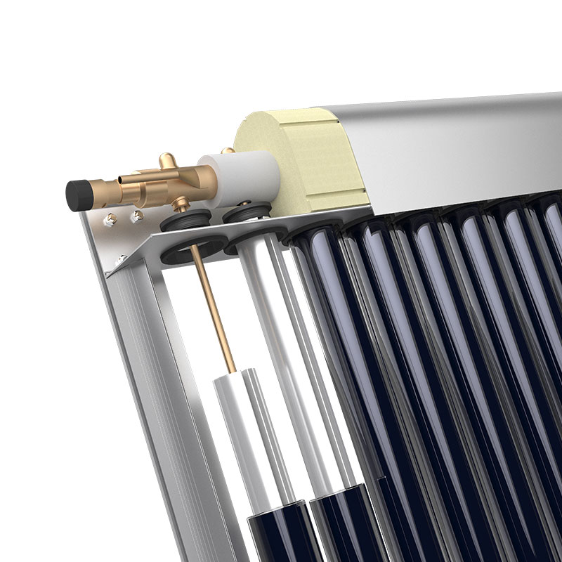
In the gravity-return arrangement described in the SOLETKS HPC product guide, heat collected in the tube evaporates a working fluid. Vapour carries heat toward the condenser at the manifold, and condensate returns toward the lower part of the heat pipe.
The angle of that heat pipe affects the return path. This is a different consideration from the angle that produces the best solar exposure over a year. An installation must satisfy the product’s operating requirements before its annual solar yield is optimized.
Manufacturer instructions are model-specific. For example, Apricus’s heat-pipe explanation recommends 20–80° for its described design, states that it does not work horizontally, and notes reduced output vertically. Those are Apricus statements, not SOLETKS HPC operating limits. They also show why assuming that every increase in inclination improves heat-pipe performance would be incorrect.
The SOLETKS public guide requests confirmation of installation angle against the current datasheet or project drawing. Obtain the permitted range for the exact HPC model and heat-pipe version being supplied. In particular, distinguish a preferred solar orientation from a minimum or maximum operating inclination.
The limiting mechanism is liquid return, not just solar incidence
Evaporation and condensation can move substantial heat with a small internal mass flow because each kilogram of working fluid carries latent heat. In a gravity-return pipe, the liquid must return down the pipe while vapour travels toward the condenser. Liquid-film resistance and the interaction between the opposing flows affect the available heat-transport capacity.
This differs from a fully wicked heat pipe, where capillary forces can assist liquid return. NASA’s thermosyphon research, section 1.2, explains the distinction and the role of gravity. That research establishes general physics; its experimental heat limits are not solar-collector or HPC ratings. The SOLETKS public description alone is also insufficient to identify every internal wick, fill or return feature of the supplied heat pipe.
For a straight pipe inclined at β above horizontal, the component of gravity along its axis is g × sin β. At 5° it is about 0.087g; at 30° it is 0.500g. The first is only about 17% of the second. This is a comparison of gravitational driving components, ne a prediction that the collector produces 17% as much heat. Fluid properties, pipe geometry, fill charge, heat input and internal construction all influence actual behaviour.
Consequently, there are two distinct design questions. Can the supplied pipe return enough liquid over its approved operating range? Within that range, which orientation delivers useful heat for the building’s season and load? Optimizing annual sunlight cannot compensate for operating outside the first boundary.
A short sunny demonstration at a shallow angle cannot settle the issue either. Starting a cold collector, running at a different heat input and rejecting heat into a hotter manifold can produce different internal conditions. Request model-specific operating-angle evidence rather than inferring approval from one observed outlet temperature.
Roof pitch, collector tilt and bracket angle are different
Three angles can appear on the same drawing:
| Angle | Reference | Question it answers |
|---|---|---|
| Roof pitch | Roof plane relative to horizontal | How steep is the supporting surface? |
| Collector inclination | Collector or tube axis relative to horizontal, as defined by the manufacturer | Does the installed product meet its operating limit? |
| Frame angle | Collector plane relative to the supporting roof or frame reference | What geometry must the mounting assembly create? |
On a simple roof section where both slopes rise in the same direction, the angles can be related directly. On a roof where the collectors face across the fall or in the opposite direction, that simple addition is insufficient. The section drawing must show the real orientation.
If the roof slopes by 5°, a flush-mounted collector may also sit at approximately 5°. Calling the roof “almost flat” does not change the collector’s operating geometry. If a raised frame is used, identify the completed collector angle relative to horizontal, not merely the adjustment marked on a bracket.
Rotating a cylindrical tube around its own axis would not change the inclination of the heat-pipe axis. Whether a tube or absorber may be rotated at all is another model-specific installation question.
What the published HPC dimensions help establish
The current HPC guide lists the following examples:
| Model | Tube count | Published outline dimensions | Published gross area | Published net weight |
|---|---|---|---|---|
| HPC182 | 12 | 1,025 × 1,920 × 131 mm | 1.82 m² | 42 kg |
| HPC240 | 16 | 1,325 × 1,920 × 131 mm | 2.40 m² | 55 kg |
| HPC298 | 20 | 1,625 × 1,920 × 131 mm | 2.98 m² | 67 kg |
| HPC370 | 25 | 2,000 × 1,920 × 131 mm | 3.70 m² | 85 kg |
| HPC442 | 30 | 2,375 × 1,920 × 131 mm | 4.42 m² | 99 kg |
The same guide lists nominal 58 mm × 1,800 mm vacuum tubes for these models. The dimensions help a designer establish the initial roof envelope and handling plan. They do not establish support-point locations, complete installed mass, approved rack geometry or the clearance needed for tube removal.
A wider module may reduce the number of separate units in an array, but it can also be harder to move through a roof access route and position between obstructions. A smaller unit may fit a constrained area more naturally. Compare the complete placement and service arrangement before choosing solely by thermal capacity.
Net weight is not a structural design load. Frames, fixings, pipework, operating fluid, any approved ballast and site loads must be considered separately.
Three areas and the operating condition implied by the power table
The product guide also lists a third area, called lighting area: 1.20, 1.60, 2.00, 2.50 and 3.00 m² across the five models. For HPC298, the three relevant values are:
| Area description | Hodnota | Appropriate interpretation |
|---|---|---|
| Rectangular outline, 1.625 × 1.920 m | 3.120 m² | Initial physical roof envelope |
| Catalogue gross area | 2.98 m² | A declared area whose boundary still needs the drawing or report |
| Listed lighting area | 2,00 m² | Consistent with the basis of the published power calculation below |
Lighting area is exactly 0.10 m² per tube in the table. The external widths also increase by 300 mm for each additional four tubes, and by 375 mm for each additional five. Assuming unchanged edge allowances and uniform spacing, these dimensions imply a 75 mm tube pitch, leaving approximately 17 mm between nominal 58 mm tubes. That is a dimensional inference, not a measured assembly drawing or an aerodynamic porosity factor.
The power entries reveal a useful second inference. Take the page’s peak efficiency 0.724 and interpret its listed 2.453 W/(m²·K) heat-loss coefficient as a linear coefficient for this consistency check:
η = 0.724 − 2.453 × (Tm − Ta)/G,
Q = Alighting × G × η.
With an inferred mean-fluid-to-ambient difference of 50 K, HPC298 gives:
| Irradiance G | Calculated efficiency | Calculated power using 2.00 m² | Published power |
|---|---|---|---|
| 400 W/m² | 0.4174 | 0.3339 kW | 0.33 kW |
| 700 W/m² | 0.5488 | 0.7683 kW | 0.77 kW |
| 1,000 W/m² | 0.6014 | 1.2027 kW | 1.20 kW |
The same calculation reproduces all 15 published model-and-irradiance entries after rounding to the table’s precision. This strongly supports a lighting-area basis and an approximately 50 K rating difference. It does not prove that 15 separate tests were performed, nor that the page explicitly declares that temperature condition. Ask the supplier to confirm the calculation and test basis.
Within this linear model, a lower mean operating temperature gives more heat at the same irradiance; a higher temperature gives less. A lower inlet temperature alone does not define the mean unless flow and outlet temperature are also known. This matters on a low-pitch roof because useful seasonal output depends on both the radiation reaching the tubes and the temperature required by the load.
HPC298’s published 1.20 kW divided by 20 tubes is approximately 60 W per tube at that stated irradiance. Its zero-loss model intercept is 0.10 × 1,000 × 0.724 = 72.4 W per tube. Apricus’s cited explanation, for its own design, contrasts heat-pipe transfer capacity above 110 W with tube output around 65 W to explain the need for transport margin. That is not evidence of an HPC capacity or angle limit. It suggests a more precise selection question: how much heat-transport margin does the supplied HPC pipe retain at the intended inclination and condenser temperature?
The public table does not provide a second-order loss coefficient or biaxial incidence-angle modifiers. An evacuated-tube array can respond differently to radiation across the tubes and along them; a flat-plate cosine assumption alone is insufficient to forecast that effect. Use model-specific incidence-angle data in the yield calculation.
The lighting-area inference still does not explain why the catalogue gross area differs from the full outline rectangle. Keep physical fit, thermal reference area and structural loading geometry separate. Dividing roof area by 2.98 m² cannot establish the number of HPC298 units that fit once shadows, access and margins are included.

Three mounting approaches to compare
1. Follow the roof with an approved flush arrangement
This can keep the collector profile relatively low and simplify the visible roof outline. It is appropriate to evaluate only where the resulting inclination, support locations and roof attachment method comply with the supplied product instructions.
Check the space below the manifold and tubes, the pipe connection route and the roof manufacturer’s attachment details. A roof that offers sufficient area can still have inconvenient seams, weak attachment locations or unsuitable access to the front of the collectors.
2. Use a raised mounting frame
A raised frame can establish an approved collector inclination independently of a shallow roof pitch. It also changes the collector height, support reactions, wind exposure and the shadow cast onto adjacent equipment or rows.
Confirm the mounting assembly as a matched system. A locally fabricated triangle with the desired angle does not automatically provide the correct collector support or roof connection.
3. Change the layout, location or collector arrangement
Sometimes the roof’s height limit, load capacity or access constraints make the preferred heat-pipe arrangement impractical. Possible responses include a different roof zone, a different approved rack, a more serviceable module layout or another collector technology whose documented installation requirements suit the building.
Where a ground field is a realistic alternative, it needs its own assessment of solar access, foundations and hydraulic routing. The separate ground-mounted collector planning guide covers that broader site decision.
Tilt changes seasonal collection as well as liquid return
Above the model’s permitted minimum angle, consider when the building needs heat. A south-facing plane at an illustrative latitude of 40°N has a solar-noon beam incidence angle of approximately:
θ = |latitude − solar declination − collector tilt|.
Using assumed solstice declinations of +23.45° and −23.45°:
| Illustrative tilt | Summer-solstice noon incidence | Winter-solstice noon incidence |
|---|---|---|
| 20° | 3.45°; cos θ ≈ 1.00 | 43.45°; cos θ ≈ 0.73 |
| 60° | 43.45°; cos θ ≈ 0.73 | 3.45°; cos θ ≈ 1.00 |
This comparison isolates the geometric beam projection at noon. It ignores diffuse radiation, the rest of the day, horizon shading and the tube array’s incidence-angle behaviour. The two candidate tilts are not HPC installation approvals.
The example shows why a shallow arrangement can favour summer beam collection while a steeper one favours winter noon collection. If the building’s hot-water load falls during summer or holidays, that shift may help reduce excess heat; a hotel with high summer occupancy may have a different optimum. A steeper frame does not itself guarantee freedom from stagnation, and it creates taller rows with a different spacing requirement.
Treat internal volume and stagnation as separate checks
The HPC table lists 0.80–1.86 L per collector under “internal / gas volume”, including 1.27 L for HPC298. That wording does not unambiguously identify liquid-filled manifold volume. If 1.27 L is confirmed as the relevant wetted collector volume, ten HPC298 units would contain 12.7 L on that basis; the arithmetic must not turn an ambiguous catalogue label into a certified hydraulic value.
In a stagnation assessment, the expansion arrangement may have to accept liquid displaced from collectors and from pipe sections reached by vapour, in addition to ordinary thermal expansion and the required reserve. Its nominal vessel volume is larger than its usable acceptance volume under the selected pressure conditions. Neither the collector count nor 12.7 L alone sizes that vessel.
The listed 120°C maximum operating temperature is also not a measured stagnation temperature or a promise that an uncooled collector stops heating at 120°C. Use the supplied model’s high-temperature behaviour and the complete loop arrangement. Tilt can change the incident load; it does not replace that protection design.
Worked geometry: how much height does a raised collector need?
This example illustrates space planning. The 30° target below is an assumed design angle, not a stated HPC minimum or an approved mounting recommendation.
Assume a simplified collector section with:
- A 1.920 m span measured along the inclined collector.
- A target inclination of 30° from horizontal.
- A roof rising at 5° in the same direction as the collector.
First calculate the collector’s vertical rise and horizontal projection:
Vertical rise = 1.920 × sin 30° = 0.960 m.
Horizontal projection = 1.920 × cos 30° = 1.663 m.
Over that horizontal distance, the roof rises:
Roof rise = 1.663 × tan 5° ≈ 0.1455 m.
The collector’s rear edge is therefore approximately:
0.960 − 0.1455 ≈ 0.8145 m
higher above the roof than its front edge, measured vertically.
This is not the required rear-leg length. The calculation omits front clearance, collector thickness, support-point positions, rack details, roof unevenness and the direction in which a particular leg is measured. Its purpose is to show why a small-looking change in roof pitch can require a substantial raised profile.
On a horizontal roof, the same simplified collector would have a 0.960 m front-to-rear rise. If the roof falls in the collector’s rise direction, the rear clearance grows rather than shrinks. A single generic bracket-height figure cannot represent all three situations.
Use the manufacturer’s mounting drawing to replace the simplified span with the actual support geometry. Then check the resulting envelope against parapets, skylights, roof plant, height restrictions and the service route.
Across the roof slope, the same frame angle produces a different clearance
Let α be the roof pitch and φ the horizontal angle between the collector’s front-to-rear rise direction and the roof’s uphill direction. For a planar roof, its elevation change over the collector’s horizontal projection B is:
Δzroof = B × tan α × cos φ.
The simplified difference between rear and front vertical clearances is therefore:
Δh = L × sin β − L × cos β × tan α × cos φ.
For the same 1.920 m span, 30° collector and 5° roof:
| Direction of collector rise relative to roof uphill | φ | Roof elevation change | Rear clearance minus front clearance |
|---|---|---|---|
| Uphill | 0° | +0.1455 m | 0.8145 m |
| Across the fall | 90° | 0 m along this section | 0.9600 m |
| Downhill | 180° | −0.1455 m | 1.1055 m |
Thus, the same collector inclination can require nearly 0.29 m more front-to-rear clearance difference when facing the opposite way on this roof. That difference can determine whether the rear edge exceeds a parapet or height limit.
This remains a section calculation. Across the roof fall, the roof may also change elevation along the collector’s width, giving different requirements at its left and right supports. A frame must support the collector in its intended plane without twisting it to meet uneven support heights. Four support elevations and the actual fixing positions are more informative than a single “25° bracket” label.
Calculate the roof-space consequence of raising the rows
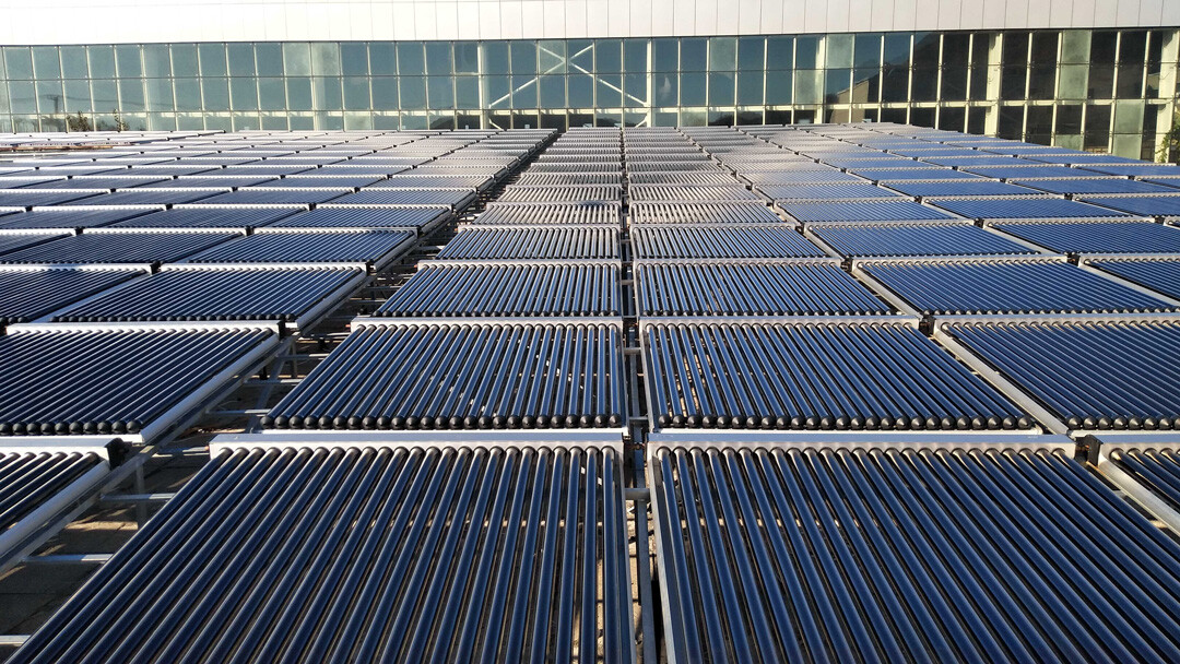
After establishing an approved operating angle, compare how alternative tilts affect the number of usable rows. A steeper collector can intercept low winter sun more directly, yet its taller rear edge can require greater spacing. Roof-level useful heat depends on both effects.
For a simple horizontal roof, take identical rows with equal front-edge heights and a sun position in front of the collector. Define the solar profile angle ψ as the sun’s elevation in a vertical section perpendicular to the rows. It equals the solar altitude only when the sun is directly in that section. More generally, for an azimuth difference γ from the row-facing direction:
tan ψ = tan(solar altitude) ÷ cos γ, for cos γ > 0.
Using collector span L and tilt β:
- Horizontal footprint B = L × cos β.
- Rear-to-front rise H = L × sin β.
- Minimum geometric gap beyond the rear-edge projection d = H ÷ tan ψ.
- Front-to-front row pitch P = B + d.
This is an envelope calculation that just avoids inter-row shading at one chosen sun position. It does not include frame thickness, tube-level shadow detail, access allowances or a weather simulation.
For L = 1.920 m and an assumed profile angle of 20°:
| Illustrative collector tilt | Horizontal footprint B | Rise H | Geometric row pitch P | Rows fitting in 10 m clear depth* |
|---|---|---|---|---|
| 20° | 1.804 m | 0.657 m | 3.608 m | 3 |
| 30° | 1.663 m | 0.960 m | 4.300 m | 2 |
| 40° | 1.471 m | 1.234 m | 4.862 m | 2 |
*For this simplified calculation, N rows occupy (N − 1)P + B. The 10 m is assumed to be available after perimeter exclusions; additional access or equipment requirements may reduce the count. The candidate angles are geometric examples, not verified HPC operating permissions. This example uses a horizontal deck, separate from the preceding 5° roof example.
The difference between two and three rows can outweigh a modest improvement in irradiation per collector, or the third row may produce little extra useful heat if the store is already satisfied. Neither outcome can be inferred from this table alone. Compare annual or seasonal delivered energy using the actual horizon, weather, load and control limits. On a sloping roof, row fronts occur at different elevations, so the flat-deck spacing formula must be replaced by the real section geometry.
Choosing a no-shade condition also involves a stated objective. Avoiding all shade during a selected winter time window usually requires more space than optimizing total annual heat. Document the selected date and hours instead of presenting one row-spacing multiplier as universally correct.
A steeper frame changes more than solar exposure
Wind and support reactions
Raising the collector changes how it presents to wind and how forces reach the roof. Review the complete load path through collector clamps, rails, frames and roof connections. Total collector weight alone cannot establish resistance to uplift, sliding or overturning.
An approved ballast arrangement, where applicable, must be designed for the roof and mounting system. Adding loose weight until a frame feels stable is not a design method.
The scale can be illustrated without assigning a site wind pressure. A bare 67 kg HPC298 weighs approximately 0.657 kN. If a separate structural assessment produced an illustrative 2.5 kN uplift resultant on an assembly, the bare collector’s weight would offset only about 26% of that force. The 2.5 kN is an assumed example, not a load rating or a ballast prescription.
The force’s position also matters. An illustrative 2.5 kN resultant acting 0.8 m from a support reference creates 2.0 kN·m of moment. The support reactions then depend on frame geometry and load combinations; they cannot be found by dividing net weight equally among feet. The mounting design must address the local roof zones, building exposure, frame behaviour, fixings and supporting structure as one load path.
Roof waterproofing and drainage
Keep drainage routes and roof inspection points accessible. Pipe penetrations, attachment points and any interface pads need to suit the roof construction. The collector installation should not create a permanent obstacle to repairing the roof beneath it.
Shadows and usable roof area
A raised rear edge changes the shadow envelope. Check actual sun positions for the period in which useful heat is most important, together with parapets and existing plant. A denser layout may contain more nominal collector area while reducing useful winter access to sunlight.
Include the shadow of the building itself as well as the collector rows. A parapet or plant enclosure can control the layout even when inter-row spacing is adequate. Diffuse irradiance and partial shadows also mean that a geometric shadow is not a direct percentage loss of annual heat.
Snow and maintenance access
Snow conditions can affect loads, access routes and the way snow collects around the installation. A steeper collector does not eliminate the need to assess the roof beneath it or snow shed into service paths. Keep this assessment separate from the heat pipe’s minimum operating angle.
Very shallow installation also warrants attention to soiling and snow retention. The component of gravity promoting runoff or sliding along the array is smaller, although glass condition, adhesion, wind and thawing still matter. The inferred 17 mm tube gaps should not be assumed to remain open under snow; bridging can change the effective covered surface. Provide access for inspection and approved cleaning rather than treating a nominal tilt or tube gap as a self-cleaning guarantee.
Design the tube replacement path before fixing the array
The installed footprint is only one part of a serviceable layout. A technician also needs a safe position from which to inspect and handle a tube, access its retention components and move the replacement part without contacting glass, roof edges or adjacent equipment.
The nominal 1,800 mm tube length is a useful reminder of the scale involved. It is not a universal instruction to leave exactly 1,800 mm of free space. The required movement depends on the collector’s removal procedure, engagement depth, tube support and the permitted handling direction.
Ask the layout to show:
- The accessible side of the manifold and the location of serviceable connections.
- The tube removal and handling envelope defined by the selected assembly.
- A working position and access path compatible with the roof’s protection arrangements.
- Clearance from parapets, ducts, other collectors and fragile roof surfaces.
- A route for bringing replacement tubes to the array and removing damaged parts.
A narrow walkway that allows a person to pass may still be unsuitable for handling a long glass component. Similarly, a panel that fits between two roof obstructions may be impossible to service there.
Treat replacement as a movement sequence on the layout: disengage the retained end as instructed, move the assembly through its permitted path, and carry it to the access route. The swept space may extend outside the installed rectangle or above a nearby obstruction. Show that envelope for the actual assembly rather than assuming a technician can rotate a long tube wherever a person can stand.
Distinguish tube access from manifold access. A layout that allows glass replacement may still leave no room to inspect a sensor pocket, insulation joint or hydraulic connection behind the manifold. Similarly, roof inspection should remain possible without dismantling an entire row. These details influence lifetime service effort, even if the first installation is straightforward.
Spare-part selection remains model-specific. Use the evacuated-tube spare assembly identification guide when confirming the replacement component rather than assuming that matching glass dimensions is sufficient.
Keep collector geometry separate from hydraulic protection
A heat pipe’s internal return mechanism is not the same as drainage of the main collector circuit. The manifold and connecting pipes still carry the system’s heat-transfer medium and need a suitable freeze, expansion and high-temperature strategy.
Raising a frame does not automatically create a drainback system. If drainback is proposed, the complete collector and pipe route must be compatible with it, including all low points and the manufacturer’s permitted arrangement. If a glycol loop is proposed, the selected fluid and system conditions need their own review.
Also check where roof pipework rises and falls around the rack. A higher collector can change pipe lengths, high points, insulation exposure and access to sensors or air-management provisions. These are part of the installed system, even though the collector’s heat pipe is sealed.
Keep three circuits or structures distinct in the design review: the sealed heat pipe, the fluid-filled manifold and external loop, and the mechanical support frame. An acceptable heat-pipe inclination proves neither freeze protection of the external fluid nor the strength of the frame. Likewise, a pressure rating for the manifold provides no wind-load rating for the collector mounting.
Four decisions to resolve before ordering
| Rozhodnutí | What the proposal should demonstrate |
|---|---|
| Product inclination | The actual installed angle is within the documented range for the supplied model |
| Roof support | The specified frame, fixings and roof interfaces have been assessed for the site |
| Physical fit | Collector height, shading, drainage and surrounding equipment are included in the layout |
| Servisovatelnost | Tubes, manifold components and roof surfaces can be reached and maintained |
For example, an approved collector angle with insufficient replacement space is still an unsuitable arrangement. Likewise, a frame that solves the thermal inclination problem may create a roof-load or height problem. Resolve the four decisions together rather than treating the angle check as final approval.
Frequently asked questions
Can an HPC collector be installed on a flat roof?
A flat roof can be evaluated with a suitable raised mounting arrangement. The selected HPC model’s permitted inclination, frame, roof support and access requirements still determine whether the proposed installation is suitable.
Can I use the roof’s existing 5° pitch?
Only if the exact model’s documented operating and mounting requirements allow that completed inclination. The publicly available HPC guide does not establish a universal 5° approval.
Is 20° the minimum angle for every heat-pipe collector?
No. A value in a particular manufacturer’s documentation applies within that documentation’s scope. Obtain the range for the actual SOLETKS collector and heat-pipe assembly being supplied.
Will a steeper tilt always produce more heat?
No. Solar exposure depends on location, orientation, shading and the required operating season. The chosen angle must first satisfy the collector’s operating limits, then be evaluated for the actual load and site.
Can net collector weight be divided by roof area to approve the roof?
No. That calculation would omit important installed components, concentrated support reactions and site loads. Roof suitability must be assessed for the complete mounting arrangement.
Request a roof-specific HPC layout
Send SOLETKS a roof plan and section showing pitch, orientation, parapets, roof equipment, access and the proposed service route. Include the preferred HPC model, roof construction, project location and any height constraints.
Request the collector’s allowed inclination range together with a mounting drawing. The useful result is a product and frame arrangement that fits the building’s physical limits and can be maintained after installation.
Sources and calculation basis
- SOLETKS HPC Heat Pipe Solar Collector Guide: published heat-pipe description, dimensions and net weights, checked on September 30, 2026. The installation-angle requirement remains subject to the current model documentation.
- Apricus — Heat Pipes: its described 20–80° operating recommendation, horizontal/vertical behaviour and the distinction between tube output and heat-pipe transfer capacity; relevant passages checked September 30, 2026. These values are not HPC limits or performance data.
- NASA Technical Memorandum 2013-216536, section 1.2: the distinction between gravity-return thermosyphons and fully wicked heat pipes. Its experimental results are not applied as HPC performance data.
The inferred 50 K power-table basis, tube pitch and conditional internal-volume calculation are explicitly distinguished from manufacturer-confirmed specifications. The directional roof geometry, seasonal beam comparison, row-spacing table and load-scale examples use stated assumptions. They are not SOLETKS rack drawings, structural assessments, annual thermal-output predictions or installation authorizations. The numerical approved inclination range, gross-area boundary and meaning of the internal/gas-volume entry still require the supplied model’s documentation.