

1. What Makes Rooftop PVT Different From Conventional PV?
Conventional photovoltaic arrays primarily generate electricity. Liquid-based PVT equipment adds a thermal absorber and fluid circuit that can transfer useful heat to a storage tank, heat exchanger, suitable heat-pump source or another approved building-energy application. The two outputs are coupled at the collector but need separate performance and safety assessments.
| Design area | Conventional PV | Liquid-based PVT |
|---|---|---|
| Electrical generation | PV modules and inverter | PV modules and inverter |
| Thermal function | No dedicated heat-recovery circuit | Absorber, connections and circulating fluid |
| Roof services | Mounting and electrical cables | Mounting, cables, supply/return pipes and supports |
| Hydraulic design | Not normally part of PV array | Flow, pressure drop, pipework, valves and fluid compatibility |
| Building integration | Electrical distribution and monitoring | Electrical distribution plus thermal load, storage or heat-pump interface |
| Zprovoznění | PV safety and operational tests | PV tests, thermal tests and combined operation |
| Údržba | Electrical and mechanical | Electrical, mechanical and hydraulic |
For a hotel, useful heat might serve preheating before the domestic-hot-water plant. For a different building, the recovered heat may be suitable only as a source for a heat pump. The temperature, timing and amount of actual usable heat must be checked against the load.
Four boundaries must remain distinct: PV electricity generated; thermal energy transferred into the PVT fluid; usable heat delivered at the building interface; and auxiliary electricity used by pumps, heat pumps and controls. These quantities cannot be turned into a guaranteed payback simply by adding PV watts and thermal watts.
EPC takeaway: Evaluate PVT as one integrated electrical–thermal installation while preserving clear acceptance criteria for each subsystem. The general SOLETKS product range is described on the PVT hybridní solární systémy page.
Document electrical generation at the agreed DC/AC meter, protection design and actual electrical consumption.
Check source temperatures, flow, losses, demand and the boundary at which usable heat is measured.
2. Six Design Gates Before an EPC PVT Quotation
Complete the following checks before locking the collector model and equipment list. A preliminary budget RFQ can be prepared with incomplete design data, but the unanswered assumptions must be listed openly.
| Design gate | The question to resolve | Evidence required |
|---|---|---|
| Roof structure | Can the building safely support the installed configuration? | Structural review, site loads and attachment details |
| Usable roof layout | How many modules fit after real constraints? | Dimensioned layout, shading, access, setbacks and obstructions |
| PV electrical architecture | Are module, string and inverter compatible? | Actual Voc/Isc, temperature coefficients, voltage limits, protection design |
| Thermal architecture | Can the facility use the recovered heat? | Hourly loads, required temperatures, hydraulic concept |
| Construction interfaces | Who designs and installs every connection? | Waterproofing, routing, mounting and responsibility drawings |
| Acceptance and procurement | What is being supplied and how is it verified? | Model TDS, scope/BOM, tests, commissioning and warranty documents |
Procurement implication: A PVT module-only quotation, a complete rooftop collector-field package and a turnkey heat-and-power system are different commercial scopes. Identify which one the EPC actually needs.
3. Rooftop Structural Assessment, Layout and Shading
3.1 Verify fully installed weight and applicable loads
A PVT collector may contain the photovoltaic laminate, thermal absorber, channels or tubes, manifolds, fittings, heat-transfer fluid and structural frame. The governing roof load is not just the manufacturer’s dry module mass.
The structural assessment should consider:
- Module dry mass and fluid-filled mass where applicable.
- Mounting rails, clamps, anchors and supporting members.
- Thermal pipework, insulation, supports and any other rooftop equipment.
- Site-specific wind uplift and downward loads.
- Applicable snow, seismic and maintenance loads.
- Roof condition, corrosion, previous modifications and existing equipment on retrofit sites.
Obtain the precise model dimensions, load data, mounting zones and filled-weight information from the supplier. The structural engineer must determine the applicable load combinations under local building rules. Do not approve PVT roof loads from a conventional PV panel’s typical weight.
3.2 Estimate usable area rather than gross roof area
The roof footprint is not the collector installation envelope. Equipment, obstructions, maintenance and emergency routes, code-required clearances, shading and geometry reduce usable area.
Illustrative planning example — not a SOLETKS project:
| Roof-area item | Hypothetical area |
|---|---|
| Gross roof | 480 m² |
| Mechanical equipment and no-build zones | −75 m² |
| Access routes and mandatory clearances | −95 m² |
| Remaining shaded or unsuitable areas | −30 m² |
| Preliminary available area | 280 m² |
This simple arithmetic assumes no overlap among excluded areas. The result is a preliminary usable zone, not installed collector area, approved panel count or verified site survey.
The module count must come from an approved layout using the exact product dimensions, mounting pitch, orientation, row spacing and clearances. A larger collector is not automatically a better use of limited roof space: compare annual useful electricity and heat at the actual project conditions.
3.3 Assess electrical shading and thermal distribution
Study shadows cast by parapets, rooftop plant, neighboring structures and seasonal sun angles. Electrical shading can affect string mismatch and inverter operation; thermal collection can vary among branches in the same PVT array.
The design should therefore coordinate string allocation, collector grouping, hydraulic branch balancing, roof obstacles and access routes. Identify maintenance areas before selecting final pipe and cable paths.
4. PVT Mounting, Roof Penetrations and Waterproofing
A PVT mounting solution should be treated as an interface among the module supplier, structural engineer, mounting contractor and approved roofing specialist. Conventional PV clamps or rail systems cannot be assumed compatible without checking the PVT model’s instructions.
4.1 Obtain mounting details for the exact model
| Položka | Reason to verify |
|---|---|
| Approved clamping/fixing positions | Prevent frame damage and uncontrolled local stress |
| Support span and orientation | Structural compatibility and load path |
| Mounting rail/clamp compatibility | Correct hardware, torque and materials |
| Tilt limits and thermal access | Suitable product operation and connection service |
| Wind/snow design loads | Roof fixing and structural safety |
| Thermal expansion and movement | Protection for both frame and pipe connections |
| Maintenance access | Safe inspection and replacement of components |
Building-integrated PVT elements that replace a roof covering need further building-envelope requirements; they are ne equivalent to the roof-mounted liquid-circuit case discussed here.
4.2 Resolve roof penetrations before drilling
Liquid-circuit PVT usually needs thermal supply and return paths between the rooftop collectors and building services. Penetration details should be approved by the roofing contractor and cover waterproofing continuity, compatible flashing, sleeves, thermal movement, insulation, condensation, drainage and applicable fire stopping.
The drawing should show where pipes and electrical routes pass through the roof, how they are mechanically protected and how future inspection will be possible. Avoid routing mechanical services through arbitrary openings without an approved waterproofing and warranty detail.
Recommended hold point: Inspect mounting fixings and completed waterproofing before concealment or loss of convenient access.
4.3 Keep loads off collector connections
Support thermal pipework independently as appropriate. Allow for fluid-pipe expansion, roof movement and model-specific mechanical limits. Follow the manufacturer’s handling, connection, sealing and torque requirements rather than assuming generic plumbing practices are adequate.
5. Electrical Design: Strings, Inverters and Cable Routing
The photovoltaic portion of the PVT module remains an electrical power generator. Thermal collection does not remove the need for safe DC design, overcurrent or other protection where required, switching, earthing/bonding, inverter integration and qualified work practices.
5.1 Request model-specific PV electrical data
| Datasheet parameter | EPC decision |
|---|---|
| Rated PV power and test conditions | Preliminary sizing and energy modeling |
| Voc and Isc | Maximum string voltage, current and protection checks |
| Voltage/current at maximum power | MPPT and inverter compatibility |
| Voltage and power temperature coefficients | Cold- and hot-condition performance |
| Maximum system voltage | Equipment and string-design safety limit |
| Connectors, cables and junction box | Temperature, installation and compatibility |
| Relevant test evidence | Identification of the actual quoted module variant |
The electrical engineer must calculate actual design-condition string voltages and currents. Rated PV watts alone are insufficient to authorize a string configuration.
5.2 Coordinate electrical and thermal routes
- Keep connectors protected from water leakage, moisture and condensation under approved details.
- Verify cable insulation and connector temperature ratings in proximity to thermal piping.
- Prevent maintenance of valves or fluid fittings from damaging DC cables.
- Provide cable and pipe supports, labeling, UV/weather protection and access.
- Confirm suitable electrical bonding and earthing within the site design.
- Provide safe isolation and lockout procedures for both electrical and thermal tasks.
Illuminated PV circuits can remain energized even when other equipment has been switched off. Electrical inspection, commissioning and maintenance require qualified personnel and suitable safety procedures.
5.3 Reference electrical standards appropriately
Depending on jurisdiction and product scope, the project may refer to IEC 61215-1:2021 for PV module design qualification, IEC 61730-1/-2:2023 for PV module safety, IEC 62548-1:2023 with its 2025 amendment for PV array design, and IEC 62446-1:2016 with its 2018 amendment for grid-connected PV documentation and commissioning.
A module test report does not approve the complete rooftop installation. IEC 61215 design qualification is not a guarantee of a particular service life. Check whether submitted qualification evidence covers the exact PVT construction variant, including relevant modifications to thermal components.
6. Liquid-Circuit PVT Thermal Design and Hydraulic Integration
The rooftop thermal loop is a defining design difference from PV-only installations. Its useful output must match the selected PVT collector, approved fluid and the actual heat-use circuit.
6.1 Identify the useful heat destination
| Intended thermal use | Core engineering question |
|---|---|
| Domestic hot-water preheating | Can recovered heat usefully preheat inlet water? |
| Heat-pump source | Are fluid temperature and flow inside the heat pump’s allowable source range? |
| Space-heating support | Can heat be transferred at a useful temperature to the building circuit? |
| Topení bazénu | Does heat demand coincide with collector availability, and is the exchanger suitable? |
| Process preheating | Is the required heat available at the process temperature and operating schedule? |
| Thermal storage | Does tank charging preserve useful delivery temperature and safety? |
Not every PVT application needs a heat pump, and recovered collector heat does not necessarily reach final domestic-hot-water temperature directly. Decide from the system’s actual thermal loads and equipment, not the solar module’s PV power rating.
6.2 Specify the entire hydraulic circuit
Request the selected model’s approved transfer fluid and concentration range; working-temperature and pressure limits; nominal or recommended flow information; collector pressure-drop data; connection details; fluid expansion allowances; approved filling, venting and draining procedures; and compatibility with pipework, pumps, valves, seals and heat exchangers.
The pump duty must include the complete collector and pipe circuit, not just the pressure drop through one module. Verify series/parallel grouping and flow balance under each operating state. Use temperature-dependent properties for water/glycol and other approved fluids where applicable.
6.3 Calculate measured collector heat, with a defined boundary
A useful thermal measurement at the collector-loop boundary can be estimated by:
Where Q̇ is thermal transfer in kW, ṁ is the measured fluid mass flow in kg/s, cₚ is the fluid specific heat in kJ/(kg·K), and T_out − T_in is the measured temperature rise in K.
Illustrative calculation only—not a SOLETKS product measurement:
| Assumed input | Hodnota |
|---|---|
| Mass flow | 0.20 kg/s |
| Specific heat capacity | 3.8 kJ/(kg·K) |
| Measured temperature difference | 4 K |
| Thermal transfer | 0.20 × 3.8 × 4 = 3.04 kW |
Use actual fluid properties and calibrated flow/temperature instruments. The result is instantaneous thermal power at the stated boundary, ne a guaranteed module rating, annual yield or useful heat delivered after pipe and heat-exchanger losses.
6.4 Design for freeze, overheating and interrupted flow
Protection must follow the selected model’s documented operating range and the project climate. Evaluate approved freeze-safe fluid or other manufacturer-approved freeze protection, expansion and pressure relief, high-temperature operating behavior, low-flow protection, pump/control failures and safe thermal isolation.
A building’s thermal storage may become fully charged while the collectors continue receiving sunlight; the connected thermal load may also disappear due to heat-pump faults or building controls. The operating sequence must define a safe response without assuming the PVT absorber is safe under all stagnation conditions.

7. Controls, Storage and Heat-Pump Interfaces
Solar thermal collection and a building’s heat demand rarely follow the same hourly pattern. Midday irradiation may be high even when domestic-hot-water peaks occur at other times. The controls should determine when heat can be collected, transferred, stored or safely curtailed.
7.1 Do not confuse storage purposes
| Storage type | Main reason it might be required | Design inputs |
|---|---|---|
| Source-loop buffer | Help manage source availability and temperatures | Fluid volume, safe temperature range, heat-pump source limits |
| Load-side hydronic buffer | Reduce short cycling or handle flow/load mismatch | Minimum run time, heat-pump modulation, allowed temperature swing |
| Domestic-hot-water tank | Serve building potable-water demand | Peak use, usable delivered hot water, charging/backup and hygiene limits |
They are distinct equipment decisions. A universal litres-per-kW rule is not sufficient for all buffer functions. Where a heat pump is included, refer to the exact manufacturer’s flow and performance map.
For the separate heat-pump design topic, see the SOLETKS PVT Heat Pump Control and Buffer Tank Design Guide.
7.2 Define normal and fault operating states
| State | Required system logic |
|---|---|
| Useful collector heat available | Confirm heat-transfer condition and permissible flow/temperature before circulation |
| Building demand available | Transfer heat to the approved load or charging circuit |
| Heat pump operating | Maintain rated source limits, minimum flow and other manufacturer conditions |
| Low solar availability | Prevent harmful reverse transfer; implement approved backup/source strategy |
| Heat sink full / unavailable | Follow model-specific safe high-temperature or protective mode |
| Freeze risk | Activate the specified protective strategy |
| Sensor, flow or power fault | Enter the manufacturer-approved protective state and report alarms |
| Backup heat required | Stage compliant auxiliary heat while maintaining system safety and hygiene |
These states are a control-design checklist, not ready-to-deploy controller software. Actual thresholds and interlocks must come from the final hydraulic circuit, equipment manuals and qualified controls design.
8. Electrical Output, Usable Heat and Performance Evidence
Do not judge rooftop PVT solely by advertised combined efficiency. PV electricity and collected thermal energy have different time profiles, loss mechanisms and value to the building.
8.1 Model actual PV electricity
Use the exact module characteristics and local irradiation, module temperature, shading, orientation, electrical layout, inverter efficiency and agreed operating assumptions. Rated laboratory PV watts are not the same as annual AC electricity delivered to the building.
8.2 Model useful thermal output
Use tested collector performance data, collector working temperatures, fluid flow, local weather, pipe/heat exchanger losses, connected heat demand and the storage/control strategy. Collected heat is not automatically heat delivered to an occupied space, process or domestic-hot-water outlet.
8.3 Agree on measurement points
| Output | Example agreed measurement boundary |
|---|---|
| PV energy generation | AC or DC meter specified in the contract |
| PVT collector thermal recovery | Flow and temperature difference at the collector-loop boundary |
| Useful thermal energy delivered | Heat transferred at the plant or building delivery interface |
| Auxiliary electricity | Pumps, controls, heat pump and other included equipment |
| Purchased-energy reduction | Matched baseline and measured project operation with recorded assumptions |
Specify sensor calibration, data logging intervals, commissioning tolerances and measurement uncertainty where relevant. A short startup test verifies operation at the observed conditions, not annual production or guaranteed savings.
8.4 Compare alternative solutions fairly
Compare PVT with realistic alternatives such as conventional PV plus a heat pump, or separate PV and solar-thermal collector arrays. Use the same roof constraints, load profiles, temperatures, capital costs, energy tariffs, maintenance assumptions and measurement boundaries.
PVT can be relevant where electricity and useful heat are both valuable on a space-constrained roof, but it is not automatically the lowest-cost solution for every building.
9. Choosing SOLETKS PVT Models for an EPC Project
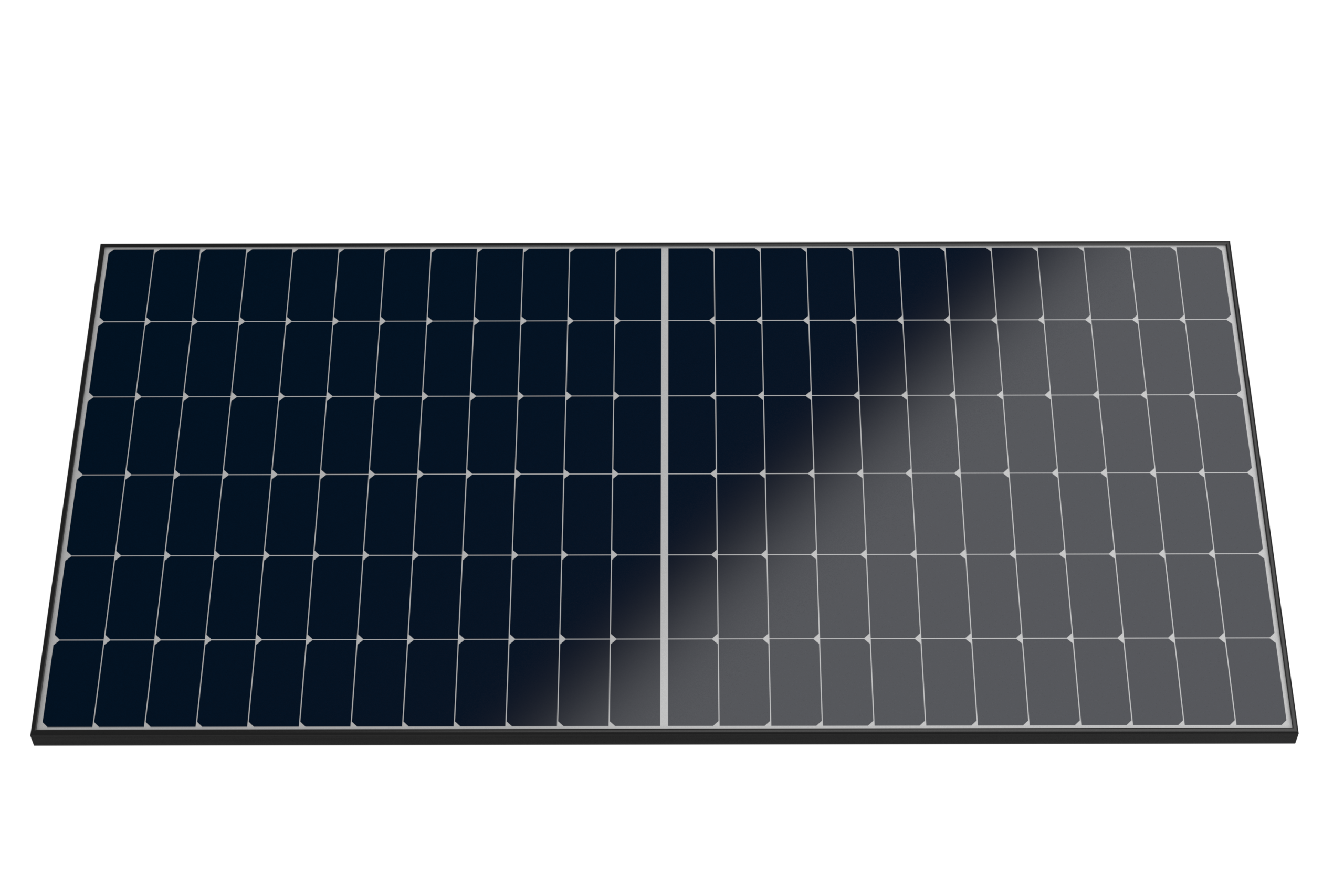
Typ PVT-E
Official product image; verify the current electrical and thermal datasheets.
View product & request TDS ↗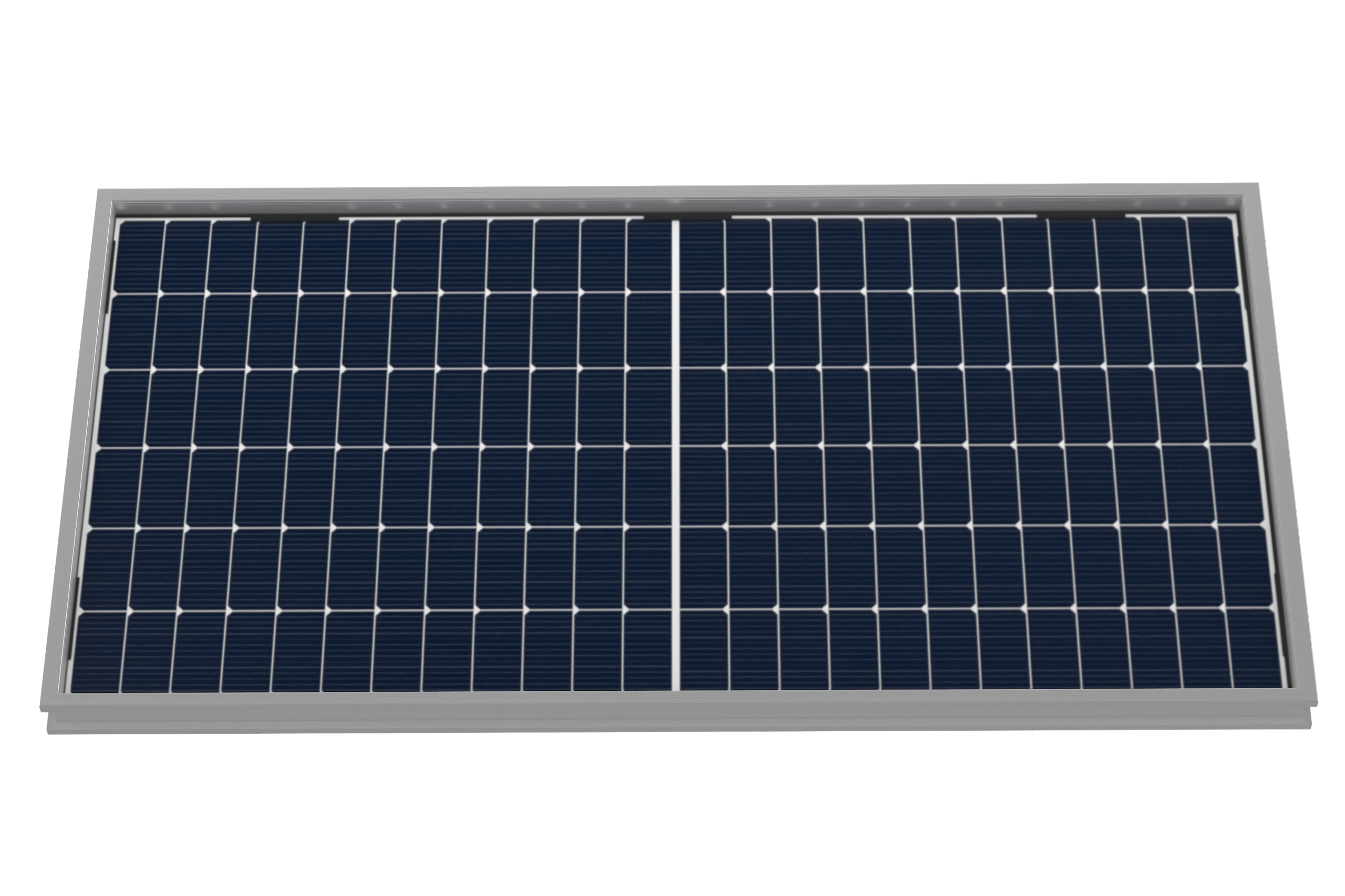
Typ PVT-T
Official product image; verify hydraulic ratings and applicable model test data.
View product & request TDS ↗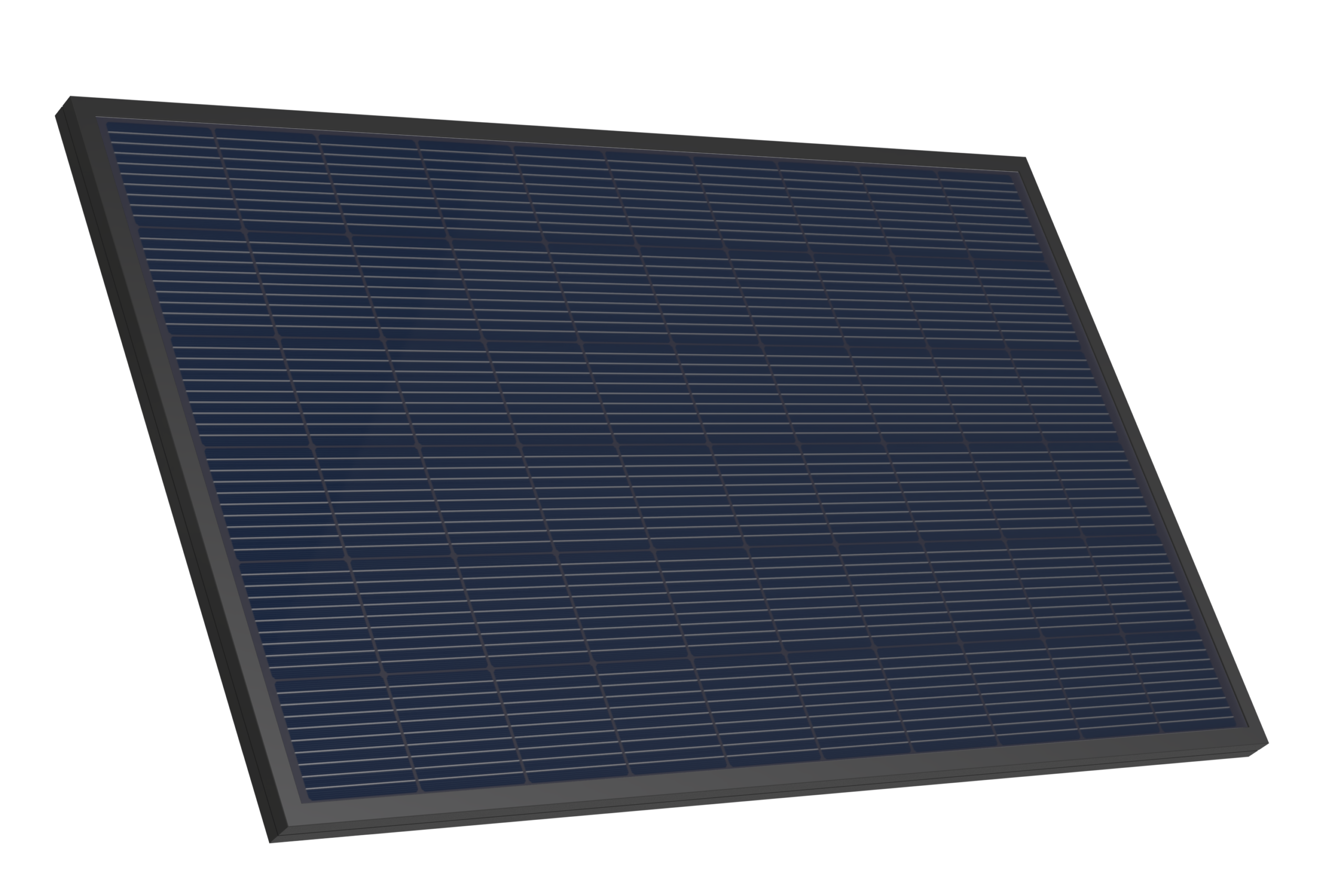
Typ TP/V Pro
Official product image; verify variant-specific mounting and integration documents.
View product & request TDS ↗SOLETKS publishes three PVT product families. A product family name alone does not verify electrical power, collector fluid rating, mounting configuration, thermal performance or service life. Request the latest model-specific documents before making a shortlist.
| SOLETKS product | First selection question | Evidence to obtain |
|---|---|---|
| PVT-E typ solárního panelu | Does this model suit the required electrical/thermal operating conditions? | Exact PV data, heat-transfer curve, dimensions and hydraulic details |
| PVT-T typ solárního panelu | Does the model’s tested thermal/electrical balance match the application? | Model thermal and electrical reports, pressure/flow limits |
| TP/V Pro typ solárního panelu | Does the project benefit from this configuration’s documented features? | Exact model datasheet, mounting, electrical and thermal interface documents |
Model identification rule: The quotation, label, technical datasheet, installation instructions and supporting test reports should identify the same module model and relevant construction variant. One model’s efficiency, dimensions, pressure rating, warranty or certificates must never be copied to another by assumption.
See the SOLETKS PVT Solar Panel product range for current published options.
Buying PVT modules for a real roof? Send SOLETKS the proposed model, roof layout, electrical target and intended thermal duty to request current mechanical, electrical and thermal documents.
Request PVT Model Datasheets on WhatsApp ↗10. EPC Interface Responsibility Matrix
A PVT installation can fail commercially even if the equipment itself is adequate: the roofer may assume the pipe penetration is the mechanical subcontractor’s responsibility, while the thermal contractor expects a pre-installed sleeve. Contract responsibility must be established before procurement and roof work.
| Work package | Typical responsible party | Deliverable / acceptance point |
|---|---|---|
| Existing roof assessment | Structural/building engineer | Structural review and applicable load design |
| Mounting and attachments | Structural/mounting contractor | Approved attachment and rail drawings |
| Roof waterproofing | Roofing specialist | Penetration details and inspection records |
| PVT module supply | Equipment manufacturer | Model TDS, limitations, instructions and actual shipped accessories |
| PV electrical system | Electrical EPC contractor | String design, protection, measurements and test records |
| Collector thermal circuit | Mechanical EPC contractor | Hydraulic diagram, fluid, pump and pressure-test records |
| Heat exchanger/storage | Mechanical system designer | Heat balance, equipment schedule and safe temperature boundaries |
| Control and monitoring | Controls/BMS integrator | I/O list, sequence, alarms and logging plan |
| Integrated commissioning | EPC commissioning lead | Combined test and handover report |
This matrix illustrates a possible division of labor. Actual responsibility follows the contract, local regulations and approved design. Hold a multidisciplinary interface review before ordering long-lead items or drilling roof penetrations.
11. Installation Inspection and Quality-Control Checklist
Quality control should be staged. A final photograph of a completed rooftop cannot verify mounting torque, waterproofing continuity, safe electrical installation or acceptable thermal fluid conditions.
Before the equipment arrives
- Confirm the approved structural survey, roof layout, clearances and access arrangements.
- Match the purchase order to the PVT model, dimensions, dry/filled mass and supplied accessories.
- Approve mounting and roof-penetration details with the appropriate contractor.
- Coordinate the electrical single-line diagram and hydraulic schematic.
- Assign responsibility for inspection, lifting, storage and site handling.
- Confirm required certificates, manuals, electrical/hydraulic data and packing list.
During rooftop installation
- Confirm fixing points, rails and clamps match the approved drawings and manufacturer instructions.
- Verify roof seals and waterproofing before concealment.
- Support DC cables and fluid pipes independently as required.
- Maintain access to junction boxes, valves, fittings, manifolds and sensors.
- Verify mechanical protection, labeling and thermal movement allowances.
- Retain model/serial identification and inspection photographs in the as-built record.
Before startup
- Complete relevant electrical tests by qualified personnel.
- Complete hydraulic leak/pressure tests using the actual component ratings and test procedure.
- Check fluid concentration and compatibility, filling, venting and flow.
- Check sensors, protective devices and control responses.
- Confirm heat-receiving equipment and backup system are ready.
- Close defects and record instrument positions and calibration where required.
Numerical pass/fail limits must come from the equipment manuals, design, applicable standards and project acceptance specification—not a generic blog checklist.
12. Commissioning: Test Electrical and Thermal Functions Together
The EPC should not accept a PVT system simply because the inverter starts. Commission the PV electrical system and thermal system separately, then prove their coordinated operation.
12.1 Electrical commissioning
The qualified electrical contractor should complete the applicable visual checks, polarity, insulation, protective equipment, inverter and monitoring tests in the approved procedure. Measurements and required documentation should follow the project’s relevant PV standards and local electrical rules.
12.2 Thermal commissioning
The mechanical contractor should verify hydraulic integrity, fluid filling, pressure, design circulation, balancing, sensors, heat-transfer behavior, heat exchanger/storage interfaces and protective responses.
12.3 Combined functional acceptance
| Acceptance condition | Example evidence |
|---|---|
| PV generation | Relevant electrical measurements and inverter operating record |
| Collector heat recovery | Flow and inlet/outlet temperatures at agreed points |
| Thermal delivery | Heat transfer to the load or storage at defined measurement boundary |
| Ovládací prvky | Results for agreed normal operating states |
| Protective functions | Safe response to approved flow, temperature and fault tests |
| Monitoring | Sensor map, data access, measurement and calibration information |
| Handover | As-built drawings, manuals, commissioning record and outstanding defects |
Where applicable, separately define factory acceptance testing (FAT) and site acceptance testing (SAT). A factory inspection does not demonstrate site-specific roof, waterproofing, wiring or hydraulic compliance.
A measured short-period startup result does not demonstrate guaranteed annual yield. If contractual annual performance is required, agree the weather-normalization, operating exclusions, monitoring boundary and verification method separately.
For further site-test planning, read Commercial Solar Thermal Commissioning Tests and Handover Checklist.
13. PVT Procurement RFQ: Technical Documents and Supply Boundary
A meaningful EPC PVT quotation needs an agreed bill of materials, design interfaces and test-document scope—not just the panel unit price.
13.1 Supplier technical document pack
Request the following for each quoted model:
- Current electrical module datasheet, power ratings and test conditions.
- Tested thermal performance and applicable collector test report.
- Overall dimensions, dry/filled mass as relevant and mechanical mounting instructions.
- DC cable, junction-box and connector details.
- Hydraulic connection drawings, flow, pressure drop, pressure/temperature limits and approved fluid.
- Suitable installation, operation and maintenance manuals.
- Applicable model-specific qualification, safety and compliance evidence for the destination market.
- Packing dimensions and handling instructions.
- Spare-parts availability and written warranty conditions.
13.2 Define what is included, optional or excluded
| Položka | Clarification for the written quote |
|---|---|
| PVT modules | Exact model, variant and quantity |
| Mounting and anchors | Included, optional or EPC-supplied; structural responsibility |
| Electrical cables and connectors | Supplied lengths, compatible parts and installer scope |
| Inverter and electrical protection | Included or furnished separately |
| Thermal manifolds and fittings | Connections, quantity and included accessories |
| Piping, valves and insulation | Supply, installation and design responsibility |
| Pumps and controllers | Included, optional or excluded |
| Heat exchanger and storage | Sized package, optional items or EPC supply |
| Heat pump and backup | System design and supply boundaries |
| Installation and commissioning | Remote support, on-site support or EPC scope |
| Dokumentace | TDS, drawings, testing, manuals, packing and acceptance records |
A quote for PVT modules only is valid if the buyer understands that it is not a turnkey building energy plant. Ambiguous exclusions are a frequent source of procurement disputes.
13.3 International purchasing requirements
Specify the destination country, module quantity, shipping method, preferred delivery term, export packing, inspection and testing requirements, model-specific documents, warranty, lead-time confirmation and spare parts. Trade terms should be agreed under an identified Incoterms edition. FOB and CIF are maritime terms; the appropriate term depends on the real shipping arrangement.
Commercial conditions, prices and delivery dates must be confirmed in the actual quotation. This article makes no claim about a guaranteed MOQ, factory lead time, project-specific certification or warranty.
14. Common Rooftop PVT Installation and Purchasing Mistakes
| Mistake | Likely risk | Correct EPC action |
|---|---|---|
| Treat PVT as mechanically identical to PV | Unapproved clamps or roof load assumptions | Obtain precise product and mounting documents |
| Calculate module quantity from gross roof area | Unbuildable roof layout | Prepare a constrained, approved array plan |
| Ignore filled mass and fluid supports | Underestimated operating loads | Calculate the complete installed configuration |
| Leave pipe penetrations to late construction | Leaks and roof warranty disputes | Coordinate waterproofing before procurement |
| Design PV cables and hot-fluid pipes independently | Safety, maintenance and routing conflicts | Issue joint electrical–mechanical services plans |
| Select circulation pump from collector area alone | Wrong design flow or high pressure losses | Calculate whole-loop duty and fluid properties |
| Assume every collected kWh is usable heat | Overstated energy savings | Compare temperature and timing with actual heat demand |
| Promise fixed PVT cooling/COP benefit | Unreliable financial projections | Use product tests and modeled operating conditions |
| Buy equipment without supply exclusions | Missing controls, accessories or storage | Require a signed BOM and responsibility matrix |
| Accept only inverter startup as commissioning | Thermal/control problems remain unseen | Complete combined electrical and thermal acceptance |
15. Frequently Asked Questions
Can PVT solar panels be installed on an existing commercial roof?
Potentially, yes. The structure, roof covering, waterproofing, installation access and site loads must be evaluated. The final approval depends on the exact PVT equipment and the building’s structural conditions.
Can conventional PV mounting rails be used for PVT modules?
Only if the selected module and mounting system allow it. PVT frames, permissible clamp positions, thermal fittings and load limits can differ from conventional PV products.
Do PVT panels always improve PV electricity output through cooling?
No fixed improvement is guaranteed. The result depends on the module’s design, cell temperature, collector fluid temperature and flow, operating schedule and weather. Use model-specific electrical and thermal data.
Does every rooftop PVT installation need a heat pump?
No. Suitable recovered heat may serve preheating, a heat exchanger or storage directly at the appropriate temperature. Other designs can use recovered heat as a heat-pump source. Match the thermal architecture to real heat demand and equipment limits.
How many PVT panels fit on a commercial rooftop?
The quantity depends on usable roof layout, model dimensions, mounting/clearance geometry, shade, structural constraints, electrical sizing and useful thermal demand. Gross roof area alone does not establish panel count.
How is thermal output different from useful delivered heat?
The collector-loop thermal transfer is measured at an agreed fluid-side boundary. Useful delivered heat is what reaches the building load under the required temperature conditions, after relevant piping, heat-exchanger and storage effects.
Does ISO 9806:2025 certification approve a whole PVT installation?
No. ISO 9806:2025 specifies relevant solar collector thermal and related tests, including for hybrid heat-and-power collectors, but excludes PV electricity-generation safety properties. Electrical design, PV safety, structural assessment, hydraulic safety and local building requirements require separate evaluation. A test conducted to an applicable standard is also not proof that every SOLETKS model holds a certificate.
What should an EPC send before requesting a PVT price?
Start with the project country, roof construction and plan, available area, PV electrical objective, thermal application, daily/hourly heat loads, temperatures, available connected equipment, expected quantity and requested supply scope. A preliminary inquiry can identify assumptions that remain open.
16. Request SOLETKS Rooftop PVT Engineering and Procurement Support
For a successful rooftop PVT project, agree how the collector is mounted, how its electricity is connected, where recovered heat is used, and which contractor is responsible for the electrical–thermal–roof interface.
SOLETKS publishes PVT-E, PVT-T and TP/V Pro product routes for photovoltaic and thermal-energy applications. The specific model and equipment supplied must be selected from approved project requirements and current technical documents.
To start a technical and commercial discussion, send:
- Project country and city.
- Building type and intended PVT application.
- Roof area, construction type, structural/installation constraints and drawings where available.
- PV output target or electrical-load profile.
- Daily/hourly heating and hot-water loads and required supply temperatures.
- Existing heat pump, storage, auxiliary heater or building-controls details.
- Desired equipment quantity, BOM scope and project delivery timeframe.
Request a PVT Rooftop EPC Review on WhatsApp
A preliminary roof drawing and energy-load summary are enough to begin a feasibility discussion. Technical selections and commercial commitments should follow a model-specific review.
Explore SOLETKS PVT Hybrid Solar Systems a PVT Solar Panel Models for existing product information.
Technical References and Further Reading
These primary resources support the engineering principles. They are not certificates for specific SOLETKS models.
- ISO 9806:2025 — Solar Energy: Solar Thermal Collectors — Test Methods. Includes hybrid collectors that generate heat and electricity; the photovoltaic electrical safety aspects are excluded.
- IEC 61215-1:2021 — PV Module Design Qualification. Qualification and type approval; not a numerical service-life guarantee.
- IEC 61730-1:2023 — PV Module Safety: Construction.
- IEC 61730-2:2023 — PV Module Safety: Testing.
- IEC 62548-1:2023 + AMD1:2025 — PV Array Design.
- IEC 62446-1:2016 + AMD1:2018 — PV Documentation, Commissioning and Inspection.
- IEA SHC Task 60 — Application of PVT Collectors and Design Deliverables.
Technical boundary: This is a general EPC design and procurement resource, not a construction drawing, product certification, warranty statement or measured SOLETKS project report. Final technical and commercial requirements must be checked against the exact models and the governing project jurisdiction.