
PVT Heat Pump Control Sequence and Buffer Tank Design
PVT heat pump control sequence guide for source-loop temperatures, COP verification, buffer sizing, sensor logic, backup staging, commissioning, and RFQ inputs.
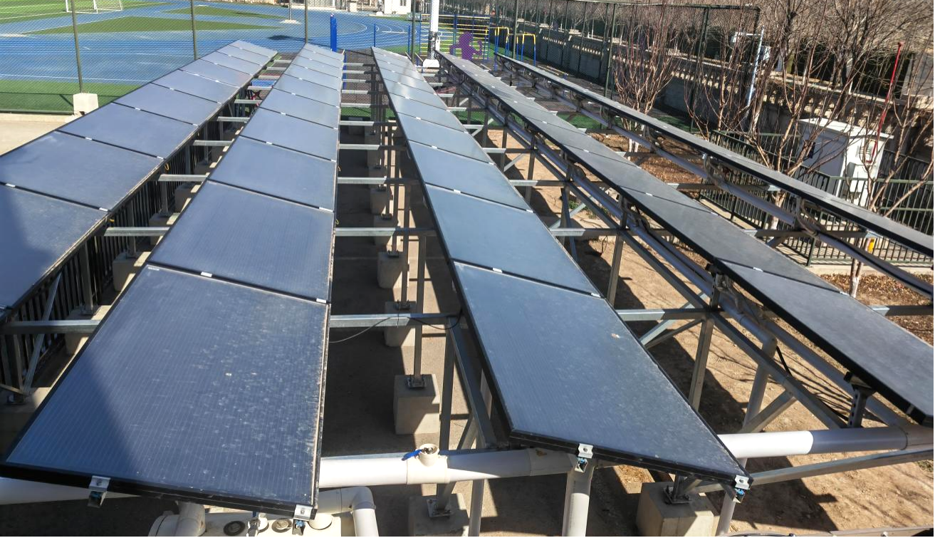
SOLETKS offers PVT panel products and supporting system-design information. This guide describes integration, controls and purchasing data that EPC teams should verify against the actual collector and heat-pump specifications. Project performance and commercial benefits require site-specific calculation and supporting evidence.
Toepassingsgebied: This is the commissioning-focused follow-up to our PVT solar panels with heat pump system overview. It concentrates on source-loop temperature control, buffer volume, sensor logic, backup staging, and acceptance measurements instead of repeating the basic architecture and application overview.
TL;DR — Kort antwoord
A PVT + heat pump system uses photovoltaic-thermal modules to generate power and exchange low-temperature heat. Suitable heat recovery may support a heat-pump source, but thermal contribution and heat-pump COP must be verified with project weather, flow, operating temperatures and the exact manufacturer’s performance map.
- Define hourly heating demand and electrical demand before choosing a PVT model.
- Verify source temperature, flow and pressure limits from the PVT and heat-pump datasheets.
- Distinguish source-loop buffer, hydronic load-side buffer and domestic-hot-water storage.
- Provide freeze, stagnation, low-source-temperature, heat-pump fault and backup modes.
- Compare PVT against PV + heat pump and separate solar thermal using identical heat and power demands.
There is no universal COP advantage or tank litres-per-kW rule. See SOLETKS PVT Hybrid Systems for current equipment choices.
1. PVT Heat Pump Design Answer
Photovoltaic-thermal (PVT) collectors can generate PV electricity and exchange useful low-temperature heat with a suitable source loop. A heat pump may then raise that heat to a temperature suitable for space heating or domestic hot water. A warmer, stable source can improve the COP of a particular heat pump at an otherwise comparable operating point—but a PVT collector is not a guaranteed warm source during all winter hours.
| Ingang | Project-specific verification |
|---|---|
| Thermal heat demand | Hourly heating and hot-water loads, peak kW, design supply/return temperatures |
| Electrical demand | PV self-consumption profile, inverter and electrical connection constraints |
| PVT thermal circuit | Manufacturer thermal curve, fluid flow/pressure drop, temperatures, freeze and stagnation controls |
| Heat pump | Model performance map at source/sink temperatures, modulation range, minimum flow |
| Buffer / storage | Purpose: source-loop stability, load-side short-cycling protection, or potable hot-water storage—do not combine these functions by assumption |
| Resilience | Backup operation, defrost/freeze protection, pump failures and cold or low-sun conditions |
For actual models, review SOLETKS PVT Hybrid Solar Systems. Request the current model TDS and corresponding heat-pump operating map for any quantitative yield estimate.
2. SOLETKS PVT Model Routes: PVT-E, PVT-T and TP/V Pro
SOLETKS publishes three PVT panel product routes. Differences in the latest electrical/thermal specifications must be checked in model-linked technical documents rather than inferred from marketing tier names.
| Product route | Vraag van de koper | Model-specific TDS to request |
|---|---|---|
| PVT-E | Is electrical generation central to the design with usable supplementary heat recovery? | PV rated performance, collector heat curve, pressure drop, connection schematic |
| PVT-T | Does the chosen application need a different balance of heat and electrical output? | Thermal/PV test data, approved temperature range, mounting and hydraulic limits |
| TP/V Pro | Would a larger or more complex design benefit from a separate engineering review? | Current model documentation, tested outputs and whole-system integration boundaries |
No model is claimed to deliver the “maximum” electrical and thermal output simultaneously without a valid common test comparison. For electricity plus air heat, see the separate Air PVT Solar Panel range.
3. Heat Pump COP: Verify the Actual Performance Map
COP = useful heat delivered (kW) ÷ electrical input (kW) for the stated test condition and measurement boundary. Heat-pump COP depends on both source-side entering fluid temperature als load-side outlet temperature, as well as heat-pump type, flow and part-load conditions.
A correct comparison uses the same machine and duty
| Comparison variable | Required control |
|---|---|
| Heat pump model | Use the same manufacturer’s rated performance map, or comparable certified model data |
| Heat delivery | Hold outlet temperature and useful output requirements constant |
| Source temperature | Use time-series PVT-loop temperatures, not a single sunny-hour estimate |
| Electrical input | Include compressors, pumps, controls and auxiliary electricity consistently |
| Seasonal comparison | Simulate hourly loads, weather, storage, cycling, backup use and PV self-consumption |
For illustration only: if a verified heat-pump map shows COP 3.0 at one operating condition and 3.6 at another with the same heat output and sink temperature, electricity per 1 kWh heat changes from 0.333 kWh to 0.278 kWh—a 16.7% reduction for that comparison point. These are mathematical example COP inputs, not SOLETKS measured PVT performance. Seasonal energy savings cannot be inferred from this pair without annual simulation.
The previous fixed COP-versus-source-temperature table and advertised winter savings were removed because they did not identify a tested heat-pump model or matched operating conditions.
4. Cold-Climate Design: Advantages and Limits
PVT thermal recovery can be useful where the building has concurrent PV and heat demand and the selected loop can supply an acceptable heat-pump source temperature. Its benefit is not guaranteed to increase with colder weather. During low-sun hours, a roof-mounted PVT surface can become cold, and long-duration source heat may be inadequate. A solar-only source loop may require auxiliary source capacity, different operating states or a different system architecture.
| Operating state | Engineering response |
|---|---|
| Sunny winter day | Compare actual available PVT thermal heat with source-loop demand and heat-pump operating map |
| Overcast / night | Check minimum permissible source temperature and available non-solar source or backup |
| Freezing ambient conditions | Verify heat-transfer fluid, pump/valve behavior, freeze protection and power-loss response |
| High PV temperature / summer | Check collector cooling, heat rejection, stagnation and how to avoid unwanted thermal charging |
| Heat pump or control fault | Stop unsafe heat exchange and hand over to an independently rated backup strategy |
Country names such as Madrid, Munich or Stockholm do not establish a fixed +27%, +52% or +78% COP uplift. Those figures, and the unverified Tianjin project COP claim, are not evidence of site-specific performance. Use measured weather and independent model test results for comparison.
5. Heat Load Calculation Before PVT System Sizing
Illustrative domestic-hot-water example, not a measured project: if the requirement is 5,000 L/day heated from 15°C to 55°C, then ΔT = 40 K and QDHW ≈ 5,000 × 40 × 0.001163 = 232.6 kWh/day. This thermal load excludes distribution, storage, recirculation and heat-exchanger losses.
Separate heat demand from PVT source contribution
| Energy flow | Correct treatment |
|---|---|
| Domestic-hot-water delivery | Measured or assumed useful energy delivered to hot-water consumers |
| Direct solar preheating | Useful solar heat that directly reduces the delivery heating duty |
| PVT as heat-pump source | Low-temperature source energy entering the heat pump; do not double count it as direct final hot-water delivery |
| Heat-pump electricity | Derive from model output/COP map at hourly actual source and load temperatures; include auxiliary pumps consistently |
| PV electricity | Calculate separately using site shading, inverter, module performance and time-matched load; do not automatically subtract all PV yield from heat-pump consumption |
If a hypothetical heat pump supplied all 232.6 kWh/day at COP 3.0, compressor-only electricity would be 77.5 kWh/day. This is a mathematical illustration only; it cannot be used to promise solar-supported COP 4.0, 8,520 kWh annual savings or a specific project payback.
Ask for hourly demand, climate, installed module model and heat-pump performance map before estimating useful PVT heat, electricity savings or buffer volume.
6. System Architecture
A practical PVT heat pump system has 5 working layers:
| Layer | Design role | Minimum data to request |
|---|---|---|
| PVT field | PV electricity + source heat | Electrical rating, thermal curve, pressure limit, flow range |
| Source loop | Moves heat to buffer tank or HX | Fluid, pump head, flow rate, freeze protection |
| cURL Too many subrequests. | Stabilizes source temperature | Volume, sensor levels, insulation, service ports |
| Heat pump | Raises heat to useful temperature | COP map, capacity, source flow, outlet setpoint |
| Backup + controls | Maintains reliability | Control sequence, alarm points, backup enable logic |
Why the buffer tank matters
Solar heat changes by minute, but heat pumps dislike short cycling:
- Short cycling → wear + lower COP + more wear
- Buffer adds thermal mass → reduces rapid start/stop → steadier compressor operation
Rule of thumb: buffer tank ≈ 15–30 L per kW of heat pump capacity, with 2-point or 3-point sensors for control stratification.
Why poor control wastes PVT heat
- Pump runs when PVT is colder than buffer → pumps heat out
- Heat pump fights solar (preheats whole tank before sunrise)
- Buffer too small → HP cycles → COP falls
For pump station + expansion sizing in the source loop, see Dimensionering van een thermisch zonne-energiepompstation en een expansievat.
7. Compare PVT + Heat Pump with Real Alternatives
| Optie | Strength | Important boundary |
|---|---|---|
| PV only + existing heating | Electricity generation with simple roof-side hydraulics | Does not inherently recover useful solar thermal heat |
| PV + air-source heat pump | Established separate equipment paths | Evaluate seasonal heat-pump performance and cold-weather backup |
| Separate PV + solar thermal + heat pump | Electrical and thermal fields can be independently specified | May need more roof area and additional hydraulic/control components |
| PVT + warmtepomp | Two potential useful outputs from the same collector area | Requires verified thermal source availability, system controls, freeze and fault strategy |
| Conventional boiler / hot-water plant | Known firm thermal capacity and backup option | Fuel cost, emissions and integration requirements differ by project |
Use a common annual load, energy tariff, installation scope, downtime allowance and measurement boundary. There is no universal 100 kWh/day minimum or country-based seasonal COP advantage that independently selects PVT.
8. PVT + Heat Pump Preliminary Decision Process
- Define both outputs: annual and hourly electrical use, hourly space-heating and/or domestic-hot-water loads, and roof access.
- Check PVT thermal usefulness: whether temperatures and thermal yield match a suitable heat-pump source or preheating application.
- Verify the heat pump: minimum source temperature, load-side temperature, minimum flow, cycling behavior and model performance map.
- Choose separate thermal boundaries: decide whether a source-side buffer, load-side hydronic buffer or potable storage cylinder is needed; size each for its own purpose.
- Design freeze, backup and electrical integration: include source shutoff, auxiliary heat, inverter and control behavior.
- Compare against alternatives: PV plus an air-source heat pump, dedicated solar thermal plus heat pump, or conventional solutions using the same demand and cost assumptions.
No universal 100 kWh/day project threshold, climate uplift percentage or fixed litres-per-kW buffer rule is sufficient to select PVT equipment.
9. PVT–Heat Pump Control Sequence
The control sequence should be implemented from a verified hydraulic schematic and manufacturers’ safety controls. The following state table is conceptual, not ready-to-deploy controller code.
| State | Entry logic | Required action and protection |
|---|---|---|
| Standby | No valid heat demand or available source capacity | Monitor temperatures, pressure, flow and alarms; keep freeze protection active where needed |
| PVT collection available | Confirmed positive useful temperature/energy differential and acceptable source return | Run source circulation within approved fluid and flow limits; prevent reverse heat transfer |
| Heat pump enabled | Heat load present; minimum source flow and temperature verified | Use manufacturer enable conditions; honor anti-short-cycle, pressure and temperature limits |
| Buffer charging | Storage charging serves a defined operational objective | Control valves and pumps; avoid mixing that destroys useful stratification |
| Backup mode | Load unmet or source/heat pump unavailable | Stage rated auxiliary heater within hygiene, scald and equipment safety limits |
| Protective shutdown | Low flow, overtemperature, loss of freeze protection, source out of range or sensor fault | Follow manufacturer fail-safe operation and alarm logging |
Minimum trend points: PVT outlet/inlet fluid temperature, entering heat-pump source temperature, load supply/return, flow rates, source-loop pressure, buffer sensor positions, compressor power, PV yield, backup runtime and faults. Agree logging intervals and commissioning tests for each operating state.
10. Lifecycle and Total Cost of Ownership
A fair comparison counts useful electricity and heat delivered, purchased electricity, auxiliary heating, service, fluid replacement, pump power, component renewal, controls and downtime. Product or component life cannot be claimed as a universal guarantee without model-specific warranty and service documentation.
| Cost or performance item | Evidence for the estimate |
|---|---|
| PVT electrical generation | Location-specific PV yield assumptions, shading and electrical design |
| Thermal heat recovery | Tested PVT thermal output curve and hourly useful-heat demand |
| Heat pump electricity | Model performance map, operating temperatures and seasonal run hours |
| Source-loop and controls | Flow, glycol chemistry, pumps, valves, metering and planned service |
| Storage / backup | Thermal losses, turnover, auxiliary energy price and peak reliability |
| Procurement / service cost | Written quotation, equipment quantities, installation, warranty and spare-parts availability |
Ask for clear assumptions, not a guaranteed COP gain or payback period. Use the PVT product specification page when requesting equipment scope.
11. Normen en documentatie
PVT projects cross solar-thermal, photovoltaic, hydraulic, electrical and refrigeration-system requirements. The current ISO 9806:2025 addresses solar collector durability, reliability, safety and thermal test methods; it replaced ISO 9806:2017. This does not establish PV electrical compliance or certify a complete building system.
| Toepassingsgebied | Request for the exact quoted equipment |
|---|---|
| PVT thermal collector | Applicable ISO 9806 edition and model-specific thermal test report |
| PV functionality | Applicable IEC 61215 / IEC 61730 documentation tied to the exact PV model, where required |
| Heat pump | Manufacturer-rated operating map, approved fluid ranges and safety requirements |
| Pressure and potable water | Relevant market-specific material and pressure documentation for supplied components |
| System controls | Hydraulic diagram, electrical schematic, alarms, freeze and failure-mode logic |
Certification obligations vary by destination market, product type and procurement requirements. Do not assume all SOLETKS PVT models possess every listed standard or certificate.
12. Invoergegevens voor offerteaanvragen voor SOLETKS
Vraag technische ondersteuning aan via de Contactpagina van SOLETKS when PVT panels, heat pump, storage, and controls need to be selected together.
Building + load
- Project city, building type, operating season
- Verwarmingsgraaddagen (HDD) for site
- Daily hot water + heating + pool + process heat load
- Cold water temperature + required delivery temperature
Existing equipment
- Existing heat pump, boiler, tank, control system
- Air-source HP COP if replacing (for comparison)
Roof
- Roof area, orientation, shading, wind exposure, service access
- Target PV capacity or electricity offset
Systeeminstellingen
- Preferred PVT tier: PVT-E / PVT-T / TP/V Pro
- Preferred heat pump source loop: water / glycol / buffer tank / HX
- Freeze protection method
Documentatie
- PVT datasheet, PV certificate, thermal curve, hydraulic diagram, wiring diagram, control sequence, packing list, commissioning sheet
13. PVT + Heat Pump Specification Checklist
| Item | Buyer information needed |
|---|---|
| Thermal demand | kWh/day, hourly profile, peak kW and delivery temperatures |
| PV electrical load | Hourly electricity use, roof area, panel electrical ratings and inverter constraints |
| PVT source | Model, usable thermal curve, temperature/flow limits, pressure drop and loop fluid |
| Heat pump | Model heat-output/COP map at actual source and load temperatures, min flow and modulating range |
| Buffer tank—if needed | Source or load-side purpose, minimum compressor runtime, load/flow mismatch and allowable temperature swing |
| Water storage—if needed | Separate potable hot-water load, charging and hygiene requirements |
| Freeze and fault logic | Fluid limits, low source temperature, power loss, high-temperature response and backup capacity |
| Evidence and quote | Product test reports, circuit diagram, installation scope, packing, warranty, lead time and commissioning plan |
Preliminary buffer-energy relationship: V (L) ≈ 860 × Pexcess(kW) × t(h) ÷ ΔT(K) for water, where excess heat input/output and allowed buffer temperature swing are established. This is a heat-capacity relationship, niet a complete hydraulic buffer design. Check minimum system volume and controls against the chosen heat-pump manufacturer’s instructions.
Veelgestelde vragen
Does PVT always improve heat pump COP by 40–80%?
No. A PVT loop is only a useful heat source when it can operate at suitable temperatures and output. Verify the heat pump map and simulate actual hourly solar and heat demand; do not apply a universal uplift.
Is a 15–30 L/kW buffer tank rule sufficient?
No. Buffer sizing depends on the heat pump’s required minimum run time, modulation, heat-load mismatch, acceptable ΔT, active circuit volume and control design. Source-loop buffer, load-side buffer and potable hot-water storage are distinct.
Is a solar PVT heat pump suitable for very cold climates?
Possibly, with an appropriate source and backup strategy. Low-sun periods, frozen fluid, heat-pump source limits and annual performance must be checked.
What documents should an EPC request?
Exact PVT TDS, PV and thermal test evidence, hydraulic scheme, heat pump performance map, controller sequences, design climate, hourly loads and operating risk assessment.
Bronnen
[1] SOLETKS, PVT Hybride Zonne-energiesystemen, PVT-T Type Zonnepaneel, TP/V Pro Type Zonnepaneel.
[2] IEA Solar Heating and Cooling Programme, Task 60: Application of PVT Collectors.
[3] U.S. Department of Energy, Heat Pump Water Heaters.
[4] SOLETKS proposal screening note: rules in comparison and lifecycle tables are preliminary engineering checks for RFQ scoping; confirm final values against local load, selected equipment, datasheets, and authority requirements.
[5] IEC, IEC 61215: kwalificatie van het ontwerp van fotovoltaïsche modules.
[6] ISO, ISO 9806:2025 Solar energy – Solar thermal collectors – Test methods.
[7] IEC, IEC 61730 photovoltaic module safety qualification.
[8] UL Solutions, Industrial Control Panels and Panel Shop Program – UL 508A.
[9] ISO, ISO 9001:2015 Kwaliteitsmanagementsystemen.
[10] ASME, Norm voor ketels en drukvaten.
[11] ASHRAE, ASHRAE Handbook — HVAC Applications, Service Water Heating + Heat Pumps.
[12] Fraunhofer-instituut voor zonne-energiesystemen (ISE), PVT Long-Term Field Performance Research.
Article updated October 9, 2026. References to unverified school, hotel or district-heating energy savings do not constitute measured evidence for PVT heat pump performance.
Heeft u een projectspecifieke technische beoordeling nodig?
Geef SOLETKS informatie door over het klimaat ter plaatse, de dagelijkse belasting, eventuele beperkingen met betrekking tot het dak of de technische ruimte, het productassortiment en de vereiste documentatie, zodat het engineeringteam een praktisch en commercieel verantwoord advies kan geven.
Discuss PVT Integration on WhatsApp ↗