
Ground-Mounted Flat-Plate Solar Collectors: Layout, Access and Hydraulic Planning
Plan a ground-mounted flat-plate collector field around solar access, row spacing, wind and snow, foundations, headers, flow balancing and maintenance.
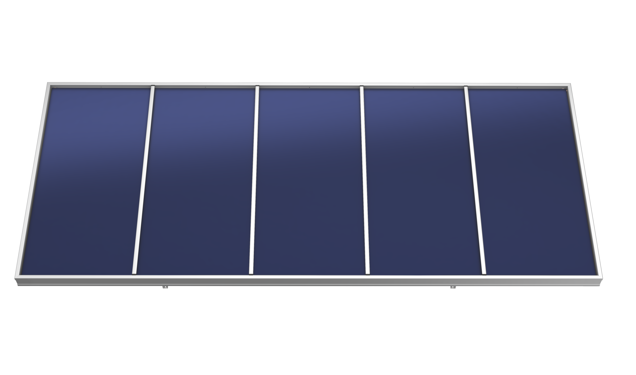
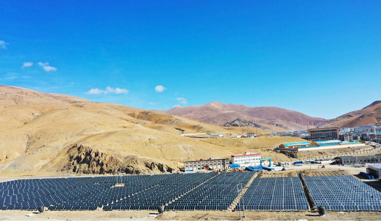
Moving a solar collector from a roof to the ground does not make the project simple. A ground-mounted field has more freedom for orientation, row spacing and service access, but it also creates new decisions about foundations, drainage, wind, snow, security, pipe length and hydraulic balancing.
The best design starts with the load and the site, then chooses the collector field and mounting system. Do not order a quantity of panels before the team has checked solar access, structure, headers, pump duty and maintenance routes.
This guide is for EPC teams, commercial owners and distributors preparing a ground-mounted flat-plate collector quotation. It is a planning framework, not a stamped structural design or a substitute for the current SOLETKS flat-plate collector datasheet.
What this guide adds
The site already contains dedicated pages for large-size collector dimensions, collector hydraulic pressure drop in collector durability. This article joins the interfaces that are easy to miss when those subjects are reviewed separately: civil layout, solar access, row spacing, field zoning, maintenance routes and the documents needed for a ground-mounted quotation.
The short answer
A ground-mounted flat-plate field is ready for detailed quotation only when five interfaces are defined:
- Solar access: orientation, tilt, row spacing, shading and seasonal operating priority.
- Structure: soil, foundation, wind, snow, corrosion, drainage and local permitting.
- Hydraulics: collector banks, headers, pipe lengths, pressure loss, flow balancing and pump control.
- Load: storage, heat exchanger, hot-water or heating demand, backup and overheat strategy.
- Service: walkways, isolation points, cleaning, vegetation control, safe lifting and replacement access.
If one of these interfaces is missing, the collector count is only a preliminary number.
The minimum drawing package
Before the supplier prices a large field, ask for five coordinated documents. They can be preliminary, but they must use the same collector model, row count and orientation:
- Site plan: boundaries, coordinates, north arrow, shading objects, setbacks, drainage and vehicle access.
- Array plan and section: collector dimensions, tilt, row spacing, header position, walkway and replacement clearance.
- Structural/foundation sheet: soil assumptions, foundation type, wind and snow design, corrosion class and anchor details.
- Hydraulic schematic: bank boundaries, headers, pipe sizes, valves, meters, sensors, pump duty, drains and relief devices.
- Operations map: isolation points, safe access, lifting route, cleaning area, vegetation control and spare-part identification.
If a quote contains only a panel count and a unit price, these interfaces have not yet been coordinated.
Start with the useful heat demand
Flat-plate collectors are heat-capturing components, not complete hot-water plants. The SOLETKS product catalogue covers collector families, while the complete system also needs storage, pumps, controls, heat exchangers, expansion equipment, valves, insulation and backup heating.
Before drawing the array, record:
- daily and seasonal heat demand;
- cold-water inlet and target temperatures;
- peak load and recovery window;
- operating hours and shutdown periods;
- storage volume and backup heater;
- acceptable solar contribution or solar fraction;
- available land, setbacks and future expansion area.
The useful output of a field depends on solar resource, collector temperature, flow, pipe loss, storage and load timing. A large field can underperform if the tank is full, the pump is incorrectly controlled or the heat has nowhere to go.
1. Plan the solar access and row layout
Orientation and tilt
Choose orientation and tilt from the project’s solar resource, operating season and land constraints. A field that prioritises winter heat may need a different tilt from a field designed around summer domestic hot water. State the design priority instead of copying a standard angle from another site.
Use a solar-access study to check the critical low-sun periods within the operating schedule. Record nearby buildings, trees, poles, terrain and future development. “No shade at noon” is not a sufficient assessment for a long collector row.
Row spacing and inter-row shading
Row spacing is a tradeoff:
- tighter rows use less land but can shade one another and restrict access;
- wider rows reduce shading but increase pipe length, foundations and land cost;
- steep winter-priority rows may need more spacing than a summer-only field;
- the collector frame, header position and maintenance route can be more limiting than the glass area.
There is no universal spacing value. Use the site latitude, design dates, collector dimensions, tilt, row height and acceptable shading loss in the layout calculation. Show the critical sun angles and the row that receives the worst condition.
A repeatable shading check
Use the same sequence for every layout revision:
- Mark the operating months and the hours when the load actually needs solar heat.
- Model the collector top edge, lower edge, tilt and row-to-row height difference.
- Test the relevant low solar-elevation angles on the selected design dates, not only noon on the equinox.
- Identify the row and time with the worst shade, then record the assumed loss or acceptance rule.
- Recheck the result after changing tilt, row spacing, header position or maintenance aisle.
This method produces an auditable design choice without pretending that one universal spacing ratio fits every latitude and load schedule.
Expansion and replacement space
Reserve space for a future bank, a lifting route and a temporary work area. A field that uses every available metre on day one may make a broken collector, valve or sensor difficult to replace. Ground mounting is valuable partly because it can provide service access; do not design that advantage away.
2. Check the ground and the mounting structure
Soil, foundations and drainage
The foundation concept depends on soil bearing, frost, groundwater, slope, drainage and local construction practice. Confirm whether the site needs driven piles, concrete footings, ballast or another solution through a qualified local designer.
Keep water away from the frame and collector base. Standing water can accelerate corrosion, undermine foundations and make winter access unsafe. Show surface drainage, cable and pipe crossings, inspection points and the route for maintenance vehicles before finalising the row locations.
Wind and snow
Flat-plate collectors, frames and headers all receive environmental loads. Ask for the design wind and snow conditions for the site and confirm that the proposed frame, anchors, clamps and collector attachment points are rated for them. The collector product page is not a substitute for the local structural calculation.
Do not assume that a heavier foundation automatically solves wind uplift, or that a snow rating for one mounting orientation applies to another. The frame, foundation and collector must be reviewed as one system.
Corrosion and material compatibility
Ground fields may be exposed to irrigation water, coastal salt, fertiliser, dust or industrial vapour. Confirm the frame, fasteners, pipe supports and protective coatings for the environment. Keep dissimilar metals separated where the design requires it, and make the replacement material specification part of the RFQ.
3. Divide the field into hydraulic banks
A large collector field should normally be divided into banks or rows that can be isolated, balanced and serviced. The exact grouping depends on collector pressure loss, recommended flow, header arrangement, elevation and pump duty.
The hydraulic drawing should show:
- bank boundaries and collector quantity per bank;
- supply and return headers with lengths and diameters;
- isolation valves, balancing valves and flow meters;
- air vents, drains, fill points and pressure relief;
- temperature and flow sensors;
- expansion vessel and heat exchanger where applicable;
- pump location, control signal and operating states;
- insulation and protection from physical damage.
Parallel rows are not balanced merely because they have the same number of collectors. Different pipe lengths, fittings and valve settings create unequal flow resistance. In a filled closed loop, row elevation alone does not add continuous pump head; high points still need adequate fill pressure and air management. Confirm the design flow and balancing method before construction.
The field-to-pump design chain
Keep the calculation order visible in the design record:
site geometry → collector bank arrangement → design flow → header and pipe sizing → pressure loss → pump duty → control range → commissioning measurement.
Changing row spacing or splitting one bank can change pipe length and pressure loss. Changing the collector model can change recommended flow and header connection. The pump selection should therefore be refreshed when the field geometry changes, not copied from an earlier concept.
Keep the pump question visible
In a fully filled closed loop, select the circulator for friction and component pressure losses at the required flow. Do not add the collector’s elevation as continuous pump head: the rising and descending fluid columns balance. Elevation still affects fill pressure and pressure at high points. Open circuits and drainback start-up require separate static-lift calculations. See Caleffi’s explanation of closed-loop head and pressure.
A pump selected only from collector count can be wrong in either direction:
- insufficient flow can raise collector temperature and reduce useful heat transfer;
- excessive flow can increase electrical use without improving the load-side result.
Ask for the design flow, total dynamic head, control range and the conditions used to calculate them. The answer should be traceable to a drawing, not only a catalogue recommendation.
4. Connect the field to storage and backup
The collector field needs a defined destination for heat. For a hot-water project, confirm whether the field charges a storage tank directly, heats a primary loop through a heat exchanger or preheats water before a boiler, heat pump or electric heater.
The connection changes the specification for:
- collector-loop fluid and freeze protection;
- heat exchanger material and duty;
- tank volume and temperature stratification;
- backup-heater control;
- overheat or stagnation response;
- hygiene and potable-water separation;
- seasonal shutdown and restart.
If the project has low summer demand, include a load-management or heat-dump strategy where required. A field that produces more heat than the tank or process can accept needs a safe operating state for sunny, low-load periods.
5. Design for maintenance before the first pour
Ground mounting makes access easier only when the layout provides it. Include:
- a clear route for inspection and cleaning;
- safe access to each bank, header, valve and sensor;
- isolation points so one bank can be serviced without shutting down the whole field;
- a lifting or handling plan for collectors and glass;
- vegetation and snow management;
- protection against vehicles, animals and unauthorised entry;
- spare parts storage and a record of model, serial number and installation position.
Ta SOLETKS service information emphasises installation support, remote troubleshooting, maintenance and spare-parts supply. Those services are most useful when the field documentation identifies every bank and component clearly.
Ground field versus roof field
| Question | Ground-mounted field | Roof-mounted field |
|---|---|---|
| Solar access | More freedom to orient and space rows | Roof geometry and nearby obstructions constrain the field |
| Struktura | Soil, foundations, drainage and security are new work packages | Roof load, penetrations, waterproofing and access dominate |
| Pipe route | Often longer, with more exposed headers and crossings | May be shorter, but vertical drops and roof access matter |
| Maintenance | Can provide safer walkways and lifting access if planned | Access may require fall protection and shutdown coordination |
| Expansion | Land can allow future banks | Roof area and structural capacity may be fixed |
| Glavno tveganje | Civil/site interface and field hydraulics | Building interface and roof safety |
The better location is the one that delivers the required solar access and serviceability at acceptable total installed risk. Ground mounting is not automatically cheaper or more efficient.
A preliminary site-to-RFQ checklist
| Topic | Information to prepare | Supplier or engineer response to request |
|---|---|---|
| Heat load | Daily and peak demand, target temperature, operating season | Collector area basis, storage and backup concept |
| Solar access | Coordinates, orientation, tilt, shading and design months | Layout with row spacing and shading assumptions |
| Land | Survey, soil, slope, drainage, frost and groundwater | Foundation concept and local structural inputs |
| Okolje | Wind, snow, salt, dust, irrigation or industrial exposure | Frame, fastener and protection specification |
| Zbiralnik | Model, aperture/gross area, pressure, temperature and flow data | Current datasheet and installation limits |
| Hydraulics | Bank count, header routes, pipe lengths and elevation | Flow, pressure loss, balancing and pump duty |
| Storage/load connection | Tank, heat exchanger, boiler, heat pump or process loop | Hydraulic schematic and control sequence |
| Varnost | Relief, expansion, freeze, stagnation and emergency states | Protection devices, setpoints and commissioning tests |
| Maintenance | Walkways, isolation, lifting, cleaning and spare parts | O&M plan and replacement procedure |
| Commercial scope | Quantity, packaging, delivery, certificates and warranty | Complete quotation boundary and exclusions |
When ground mounting is the better option
Ground mounting is attractive when the roof cannot carry the field, the project needs a large collector area, the owner wants easy access, or the land allows a well-oriented array with room for expansion. It can also simplify the separation between a collector field and an indoor plant room.
It is less attractive when land, foundations, security, long pipe runs or local permitting dominate the project cost. A roof installation may still be more efficient if it has good solar access and a short route to storage. Compare the complete installed system, not the collector surface alone.
Questions to resolve before ordering
Do not release the final purchase order until the project team can answer these questions:
- Which months and hours drive the solar-access calculation?
- What is the worst-case row shading condition?
- What wind, snow, soil and drainage assumptions support the foundation design?
- How many banks can be isolated and balanced independently?
- Where do the expansion vessel, relief devices, sensors and drains sit?
- What happens when the tank is full or the process is shut down?
- Can a technician reach every collector, header and valve without unsafe work?
- Which product values are tested data, and which are project assumptions?
- Does the quote include the frame, foundations, headers, pump station, controls, storage and commissioning—or only collectors?
Pogosta vprašanja
Is ground mounting better than roof mounting?
Not universally. Ground mounting can improve orientation, access and expansion, but it adds foundations, drainage, security and longer pipe routes. Compare the full installed system and the maintenance plan.
What is the most important ground-mount document?
The coordinated site and array drawing that shows row spacing, shading objects, foundation assumptions, headers, access and future maintenance space. A collector datasheet alone cannot resolve those site interfaces.
Can I use a fixed row-spacing rule?
Use a site-specific shading study instead. Latitude, tilt, row height, design dates, operating hours and acceptable shading loss all change the result.
Why divide a field into banks?
Banks make flow balancing, isolation, commissioning and maintenance manageable. They also let the designer connect field geometry to header size, pressure loss and pump duty.
What should a ground-mounted RFQ include?
Send the site survey, coordinates, solar-access assumptions, soil and drainage information, wind/snow conditions, heat load, collector model, field layout, hydraulic schematic, storage/backup plan, maintenance route and required certificates.
Final planning rule
Specify the ground-mounted field as a complete thermal interface: solar access, frame and foundation, collector banks, hydraulics, storage, backup, safety and maintenance. The SOLETKS large-size flat-plate collector range may be relevant to larger fields, but the correct model and quantity still depend on the load, site and current project data.
For a quotation, send the site coordinates, land survey, solar-access assumptions, daily and peak heat load, target temperature, storage and backup plan, collector area, preferred layout, environmental loads, pipe routes and required certificates. That brief lets the supplier respond with a field concept instead of a panel-only price.