
Single-Coil vs Twin-Coil Solar Hot Water Tanks: Matching Solar and Backup Heat
Choose the tank around its heat sources, exchanger duty and recovery behaviour. Coil count and nominal storage volume are only the starting points.
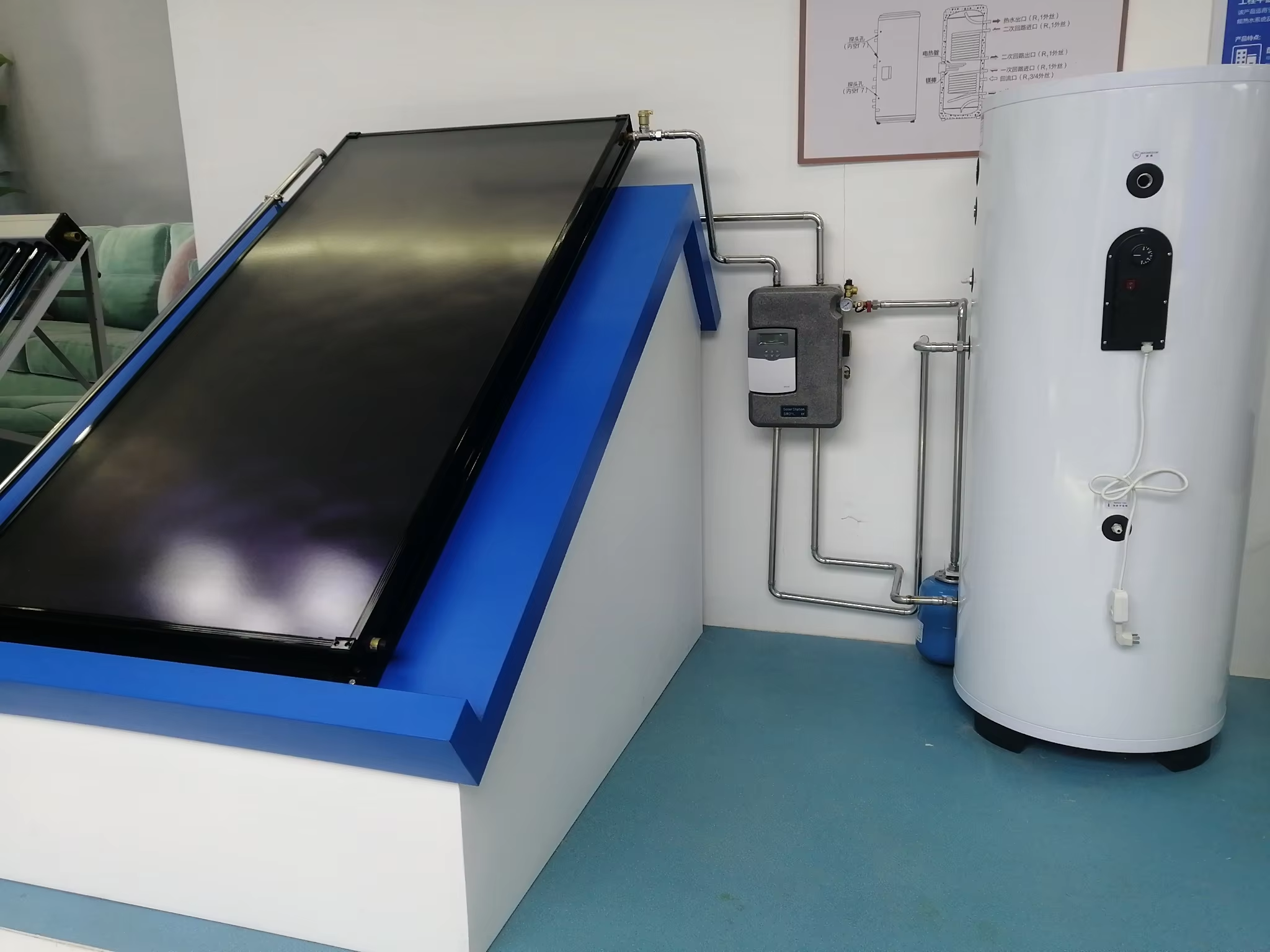
Two solar water-heating quotations can specify the same tank capacity and still deliver very different systems. One tank may have a single solar coil and an electric backup element. Another may have separate lower and upper coils for solar and boiler heat. A third may use an external heat exchanger and no internal solar coil at all.
Choosing between them is a heat-source decision as much as a storage decision. The correct tank must accept heat from the sources you actually have, transfer it at their operating temperatures and preserve enough usable hot water for the building’s demand.
For many projects, the starting choice is straightforward: a single solar coil can be sufficient when backup is electrical or provided by a separate downstream heater; a twin-coil tank is a candidate when solar and a separate hydronic heat source both need their own internal heat exchangers. Heat-pump compatibility still requires a duty check, whichever arrangement is selected.
What “single coil” and “twin coil” actually describe
An indirect coil is a heat exchanger inside a tank. Heat-transfer fluid flows inside the coil and exchanges heat with the surrounding stored water without intentionally mixing the two fluids.
A typical single-coil solar cylinder uses its lower coil for solar input. A typical twin-coil solar cylinder adds another coil in the upper region for a boiler or another compatible source. Both coils can serve the same stored-water volume; two coils do not necessarily mean two separate water compartments.
This lower-solar, upper-backup arrangement is illustrated in Viessmann’s explanation of dual-mode cylinders. It explains the general arrangement, not the specification of a SOLETKS tank.
Yang SOLETKS flat-plate split water-heater page publishes these package and tank entries:
| Listed tank size | 300 L | 500 L | 800 L | 1,000 L |
|---|---|---|---|---|
| Collectors in package | 3 × BTE-2.0 | 4 × BTE-2.0 | 8 × BTE-2.0 | 10 × BTE-2.0 |
| Listed length | 1,740 mm | 1,845 mm | 1,720 / 1,820 mm | 2,000 / 2,100 mm |
| Inner diameter | Ø480 mm | Ø580 mm | Ø800 mm | Ø800 mm |
| Outer diameter | Ø580 mm | Ø700 mm | Ø900 / 1,000 mm | Ø900 / 1,000 mm |
| Listed PU insulation | 60 mm | 60 mm | 50 / 100 mm | 50 / 100 mm |
| Expansion vessel in package | 12 L | 24 L | 50 L | 50 L |
The source table merges the 60 mm insulation entry across both 300 L and 500 L; its 50/100 mm alternatives apply to 800 L and 1,000 L. This distinction matters when extracting a table into a quotation.
Common entries include a SUS304 or SUS316L inner tank, a 7 bar tank working pressure, 1.5–3 kW electric heating at 220 V or 1.5 kW at 110 V, and Φ12 × 1.0 mm coil tube in optional copper, SUS304 or SUS316. No-coil, bottom-coil and upper-plus-bottom-coil arrangements are listed. Two pump-station options appear: SR21H with a Grundfos 15-65 130 pump and listed 60–100 W input, and TSCEN-6 with a Wilo ST20/11 and listed 165 W input. A package listing is not a completed pump selection or expansion-vessel calculation for every site.
Two immediate checks follow. For the 300 L model, the listed concentric diameters leave (580 − 480)/2 = 50 mm radially between the stated surfaces. That does not reconcile with a 60 mm insulation layer on the same geometry; drawing definitions or product versions need confirmation. For 500 L, the corresponding difference is 60 mm. Neither calculation establishes the measured standing loss.
The page also omits coil length, surface area, parallel-passage count and tested duty for each coil. Tube material and diameter cannot supply those missing heat-transfer and hydraulic characteristics. The following examples show how to use the published package information to quantify the consequence.
Several similar-sounding terms describe different things:
| Term | What it describes | What it does not establish |
|---|---|---|
| Single or twin coil | Number of internal heat exchangers | Tank capacity, pressure class or recovery speed |
| Electric immersion heater | An electrical heating element in the tank | An additional hydronic coil |
| Double-wall heat exchanger | A particular construction of the fluid-separation boundary | Two independent heat-source coils |
| Two-tank system | Two separate vessels | The number of coils inside either vessel |
| Thermal buffer | Storage used to manage a heating circuit | Suitability for storing drinking water |
Specify the stored medium as well as the coil arrangement. A heating-water buffer and a domestic hot-water cylinder are not automatically interchangeable products.

When one solar coil is enough
Solar with electric backup in the same tank
In this arrangement, the collector circuit supplies the coil and the electrical element supplies backup heat. No second hydronic source needs its own coil.
The important details are the element’s position, permitted output, thermostat and high-limit provisions, available electrical supply and the volume it can effectively reheat. An element near the upper region can restore a limited usable reserve without necessarily heating the entire tank immediately.
A second coil would add value only if it served an actual hydraulic function. It should not be purchased simply because “twin coil” sounds like a higher performance grade. Caleffi’s SolarCon material in idronics 11 provides a manufacturer example of single-coil solar tanks using electric backup, alongside dual-coil alternatives.
Solar preheat with a separate finishing heater
A single-coil tank can also provide solar preheating before water enters an existing compatible water heater. Solar heats the preheat tank; the downstream appliance raises the water to the required delivery condition when necessary.
The retained heater must accept the possible inlet temperatures and flow conditions. The arrangement also needs an appropriate bypass, control and service strategy. This is a separate question from how many coils the solar tank contains. The retained-heater interface guide covers that retrofit boundary in more detail.
One coil is therefore not synonymous with “no backup.” It means the proposed tank has one internal fluid-to-water heat exchanger.
When a twin-coil tank is the stronger candidate
A twin-coil cylinder can suit a project with a solar collector circuit and a boiler circuit that must remain hydraulically separate. The lower coil receives solar heat; the upper coil receives backup heat when the upper stored-water region needs recovery.
Conceptually, the heat paths are:
- Solar circuit → lower coil → return to collectors.
- Boiler circuit → upper coil → return to boiler.
- Potable cold water → stored-water volume → hot-water outlet.
These are three separate paths, not a mixing junction. The proposed tank’s flow and return connections must follow its actual drawing and installation instructions.
The lower location helps solar work against the cooler part of the stored water. The upper backup coil can concentrate recovery near the hot-water outlet. That separation is useful when the controller allows the lower region to retain solar-collection capacity while maintaining the required upper-zone supply.
The benefit is not automatic. Backup heating that repeatedly warms the whole tank before the solar collection period can reduce the temperature difference available for solar heat transfer. Strong circulation or poorly placed return connections can also mix the stored water. Coil layout, sensor positions and operating sequence must therefore be considered together.

Equal stored energy can provide very different useful hot-water reserves
Consider two idealized 300 L stores, with incoming cold water at 10°C:
- Store A has an upper 100 L region at 50°C and a lower 200 L region at 20°C.
- Store B is uniformly mixed at 30°C.
Both contain the same sensible energy above the incoming-water temperature:
EA = [100 × (50 − 10) + 200 × (20 − 10)] × 4.186 ÷ 3,600 = 6.98 kWh.
EB = 300 × (30 − 10) × 4.186 ÷ 3,600 = 6.98 kWh.
Yet their immediate delivery capabilities differ. The ideal 100 L upper layer in Store A can be mixed with 10°C cold water to provide:
V40 = 100 × (50 − 10) ÷ (40 − 10) ≈ 133 L at 40°C.
Store B cannot provide 40°C water without further heating, despite having the same total energy. These hypothetical temperatures illustrate stratification; they are not a potable-water storage or hygiene schedule. Real draw-off performance is affected by mixing, inlet design, losses and ongoing recovery.
This is why the useful reserve and the lower solar zone deserve separate attention. A top sensor can report satisfactory temperature while very little hot volume remains. A low sensor can demand backup heat that warms more of the tank than the next draw-off requires. A twin-coil layout offers useful separation only when its controls and hydraulics preserve the intended temperature profile.
For the separate question of how much water to store, use the commercial tank sizing and stratification guide. Choosing two coils does not correct an unsuitable storage volume.
A boiler coil is not automatically a heat-pump coil
The most consequential error in a mixed-source quotation is to assume that a coil’s advertised kW rating applies at any source temperature.
Heat transfer depends on the temperature difference between the fluid inside the coil and the surrounding tank water, as well as surface area, flow, fluid properties and the heat-transfer characteristics of the coil. A rating established with hot boiler water may be inappropriate for a heat pump operating with a smaller temperature difference.
Caleffi’s thermal-storage guidance explains why coil area and operating conditions affect the temperature difference needed for heat exchange, and why tested performance tables matter. For procurement, this leads to a practical rule: request coil output at the project’s primary supply temperature, flow rate and relevant tank-water temperatures, rather than accepting a single maximum rating.
A useful comparison includes:
| Coil characteristic | Why the buyer needs it |
|---|---|
| Heat-transfer output at stated conditions | Shows whether the coil can accept the source’s useful output |
| Primary supply and return temperatures | Identifies the source-side temperature basis |
| Tank temperature during the rating | Shows how close the calculation is to the end of recovery |
| Primary fluid and concentration | Distinguishes water data from a glycol mixture |
| Flow and pressure drop | Allows the circulator and coil to be matched |
| Coil area, position and internal volume | Describes the physical exchanger and the tank region it serves |
| Pressure and temperature limits for each circuit | Defines the permitted operating boundaries |
More coil surface can improve low-temperature heat transfer, but area alone does not supply the answer. A long, narrow passage may also increase resistance. Compare the tested duty and pressure loss together.
Follow the temperature drop across the exchanger
Heat must cross the primary-fluid boundary layer, tube wall, any deposits, and the boundary layer on the stored-water side. Their thermal resistances act in series. Using total resistances in K/kW, rather than mixing coefficients based on different surface areas:
1/(UA) = Rinside + Rwall + Rfouling + Routside.
Here UA is the overall thermal conductance in kW/K. Increasing tube-wall conductivity addresses only one term. If water-side convection or a deposit dominates, a more conductive tube wall may change total transfer much less than expected.
The corresponding exchanger relation is Q = UA × ΔTlm, where ΔTlm is the logarithmic mean driving temperature difference. The primary fluid cools as it crosses the coil, so its inlet temperature minus tank temperature is not the driving difference everywhere. MIT’s heat-exchanger notes develop this temperature variation and the logarithmic-mean relationship.
For selection, the consequence is simple: a coil must work at the small temperature difference near the end of recovery, not merely accept a high rate when the tank is cold. Raising the heat-pump flow-temperature setting to overcome an undersized coil can also change source performance; the cylinder and heat pump should be evaluated as a combination.
Do not connect two independent sources to one coil merely because there are two convenient pipe connections. Those connections are usually the inlet and outlet of the same exchanger. Shared-source arrangements require a specifically designed hydraulic and control scheme.
What a heat-pump cylinder test measures
The UK Hot Water Association’s HWA 002:2020 separates heat-pump cylinder assessment from conventional boiler conditions. Its generic Class 1 procedure uses 0.42 L/s primary flow at 55°C, starting the cylinder at 10°C and heating to a 50°C control-sensor target. Its introductory boiler comparison is 80°C at 0.25 L/s.
The subsequent 0.25 L/s draw-off measures usable water down to a 40°C outlet threshold; at least 70% of net capacity must be delivered at or above that threshold. The specified reheat calculation is:
P = (Tav − 10) × Vh ÷ (14.3 × M),
where Vh is qualifying draw-off volume in litres, Tav its average temperature in °C, and M reheat time in minutes. The specification also addresses exchanger hydraulic resistance and additional heat exchangers. This is an industry test specification, not a declaration that a SOLETKS tank has passed it.
For an invented result of 225 L delivered at an average 45°C after a 50-minute reheat, the equation gives 11.0 kW. The 14.3 constant approximates 60/4.186; this is an average test result, not an instantaneous coil rating. If net capacity were 300 L, the delivered fraction would be 75%. Those two numbers answer different questions: how rapidly energy was restored and how much usable hot water was available afterward.
Within the MCS certification scheme, MIS 3005-D:2025, clauses 3.5.4–3.5.7 calls for manufacturer-compatible cylinder heat exchange, notes the larger surface area often needed at heat-pump temperatures, and specifies at least 55°C flow capability at its defined design conditions when serving a cylinder. It also requires a means of controlling bacterial growth. These are requirements within that document’s scope, not universal operating settings for every market.
For procurement, request the test’s primary temperature and flow, recovery time, usable delivered volume, sensor endpoint and resistance curve. For a twin-coil cylinder, identify which coil each result concerns. A heat-pump result for one coil cannot qualify the solar coil or the other backup coil by association.
Worked example: the backup source is large enough, but is the coil?
Assume a buyer wants a defined 200 L backup-heated volume to rise from 25°C to 50°C within one hour. These are calculation assumptions, not recommended storage or hygiene settings.
Taking water density as approximately 1 kg/L and specific heat as 4.186 kJ/(kg·K):
Required energy = 200 × 25 × 4.186 ÷ 3,600 = 5.81 kWh.
To provide this energy in one hour, the average heat transfer into that volume must be at least 5.81 kW, before tank losses or simultaneous hot-water use are included.
Suppose the proposed backup source has a nominal 10 kW output. That rating does not prove one-hour recovery. The source must deliver the necessary output under the actual water-heating conditions, and the coil must pass it into the tank throughout the warming cycle.
If the actual average transfer through the coil were only 4 kW, the idealized recovery time would be:
5.81 ÷ 4 = 1.45 hours, or about 87 minutes.
The one-hour requirement would not be met, even before losses and draw-off. Installing a larger upstream heater would not solve a heat-transfer bottleneck at the coil.
The number to request is the recovery performance of the source-and-cylinder combination at the intended conditions. Because the driving temperature difference falls as the tank warms, a rating at the beginning of recovery cannot safely be treated as the average for the whole cycle.
Also verify the heated volume. A 300 L tank with an upper coil does not necessarily provide 300 L of rapidly recovered backup storage. Its usable volume depends on coil position, stratification, sensor location, draw-off and the manufacturer’s tested behaviour.
Calculate the slowdown as the tank approaches the source temperature
A simplified dynamic model makes the issue visible. Assume the 200 L heated volume is perfectly mixed, the primary inlet temperature Ts is constant, there is no draw-off or heat loss, and an effective coil conductance K remains constant. Then:
Q(t) = K × [Ts − Ttank(t)].
K is not identical to UA: it also accounts for the primary fluid cooling as it travels through the coil. For a uniform surrounding tank temperature and fixed properties, an idealized relation is:
K = Cprimary × [1 − exp(−UA/Cprimary)],
where Cprimary = ṁ × cp is the primary stream’s heat-capacity rate in kW/K. This follows from the distributed tube heat balance; the effectiveness and heat-capacity-rate method is also explained in Caleffi’s heat-exchanger guidance.
The tank heat capacity is Ct = 200 × 4.186 ÷ 3,600 = 0.2326 kWh/K. Integrating Ct × dT/dt = K × (Ts − T) gives the recovery time in hours:
t = (Ct/K) × ln[(Ts − Tstart)/(Ts − Tfinish)].
Using an assumed K of 0.30 kW/K gives:
| Modelled condition | Primary inlet at 55°C | Primary inlet at 75°C |
|---|---|---|
| Tank warming interval | 25 → 50°C | 25 → 50°C |
| Initial transfer | 9.0 kW | 15.0 kW |
| Transfer at 50°C | 1.5 kW | 7.5 kW |
| Calculated recovery time | 83 minutes | 32 minutes |
The same simplified coil model takes far longer at the lower source temperature because its driving difference falls to just 5 K. Dividing 5.81 kWh by the initial 9 kW would predict about 39 minutes, less than half the integrated result. That shortcut fails because it assumes the initial transfer continues throughout recovery.
These are explanatory calculations, not tested SOLETKS recovery times. K can change with temperature and flow, and a real stratified cylinder requires more than one tank-temperature node. The source must also sustain the assumed inlet temperature: the 75°C example initially requires 15 kW, so it cannot describe an uncapped 10 kW source. Where source capacity is lower, the source limit and its control response must be included in the transient calculation.
The equation also shows why “almost reaching” the source temperature is difficult. As the requested finish temperature approaches Ts, the logarithm grows sharply. At equal tank and source temperatures, this passive exchanger has no driving difference for further heating.
More primary flow has diminishing thermal returns
For illustration, 500 kg/h of water with cp = 4.186 kJ/(kg·K) has Cprimary ≈ 0.581 kW/K. With assumed UA = 0.50 kW/K, the model gives K ≈ 0.335 kW/K. Doubling UA to 1.00 kW/K at the same flow gives K ≈ 0.477 kW/K, an increase of about 42%, rather than 100%.
Alternatively, hold UA at 0.50 kW/K and double the flow to 1,000 kg/h. K increases to approximately 0.406 kW/K, only about 21% above the original value. That thermal improvement must be assessed alongside the additional pumping requirement. Both comparisons deliberately hold other properties constant to show the model’s limits.
There are two limits: at very high flow, K approaches UA; with very large UA at fixed flow, K approaches Cprimary. In practice, UA itself can change with flow, and the circulator must supply the resulting pressure drop. A larger pump cannot remove every thermal bottleneck, just as adding surface cannot remove every flow-capacity limit. Use the correct properties for the actual water or glycol mixture at its operating temperature.
Why two coils with similar area can need different circulators
The tube’s outside area helps heat transfer; its inside diameter strongly influences velocity and pressure loss. These are related design choices, but they are not interchangeable performance ratings.
Consider two invented tube arrangements, not SOLETKS coil specifications, carrying 0.10 L/s of water:
| Illustrative arrangement | A: narrow and long | B: wider and shorter |
|---|---|---|
| Outside diameter / wall thickness | 12 / 1 mm | 22 / 1 mm |
| Inside diameter | 10 mm | 20 mm |
| Tube length | 20 m | 11 m |
| Outside area, π × OD × length | 0.754 m² | 0.760 m² |
| Mean internal velocity | 1.27 m/s | 0.318 m/s |
Using the Darcy–Weisbach relation Δp = f × (L/D) × ρv²/2, an assumed Darcy friction factor of 0.03 and density of 1,000 kg/m³, the straight-tube portions would lose approximately 48.6 kPa dan 0.84 kPa, respectively. This deliberately simplified comparison excludes curvature, fittings and property changes; a real helical coil requires its measured resistance curve.
The common 0.03 factor is a stated comparison assumption, not a property of both tubes. For example, using water with an assumed kinematic viscosity of 1.0 × 10⁻⁶ m²/s near 20°C, arrangement B has Reynolds number about 6,400. A smooth-tube Blasius estimate gives f ≈ 0.035, raising its straight-tube estimate to about 1.0 kPa. This sensitivity does not change the large geometric difference, but it shows why temperature, fluid and flow must accompany a resistance estimate.
The result is not a recommendation to choose arrangement B: equal outside area does not guarantee equal UA, and its lower velocity also affects internal convection. It demonstrates why “0.75 m² coil area” is insufficient for pump selection. The system’s available differential pressure must intersect the coil-and-pipe resistance at a flow that also meets the heat-transfer requirement.
For a twin-coil quotation, require separate data for the lower and upper coils. They may have different lengths, positions and pressure losses. A duty claimed for the lower solar coil cannot automatically be assigned to the upper backup coil.
Screen the Φ12 coil against the listed three-collector package
The same SOLETKS page gives a BTE2.0-2 aperture area of 1.87 m² and lists three BTE-2.0 collectors with the 300 L package. If the package uses that specified collector variant, the aperture totals 5.61 m². Confirm the model designation when ordering.
Assume that field supplies 2.8 kW during an illustrated operating period, and the coil must pass it at an 8 K logarithmic mean driving difference. Required conductance is:
UA = 2.8 ÷ 8 = 0.35 kW/K.
Using a sensitivity range, not a measured SOLETKS value, of U = 250–400 W/(m²·K), the outside surface requirement is 0.875–1.40 m². A single plain Ø12 mm tube would require:
L = A/(π × 0.012) ≈ 23–37 m.
Now assume a field flow of 36 L/h per m² of aperture: 5.61 × 36 ≈ 202 L/h, or 0.056 L/s. Through a nominal 10 mm bore, velocity is approximately 0.71 m/s. Using water properties near 40°C—density 992 kg/m³ and kinematic viscosity 0.658 × 10⁻⁶ m²/s—Re is about 10,900 and a smooth-tube estimate gives f ≈ 0.031.
The corresponding straight-tube loss is approximately 0.78 kPa per metre, giving 18–29 kPa, or 1.9–3.0 m of water head, over that assumed coil length. A real helix, connecting fittings, collectors and site pipework add their own resistance. Glycol requires recalculation with its actual concentration and temperature; the water result should not be reused unchanged.
This is a useful screening outcome: a seemingly small tube specification can imply metres of pump head before external pipework is counted. Parallel passages could change the result substantially. The listed pump name or electrical input does not establish available head at 202 L/h; use its exact speed-dependent operating curve and the complete circuit. These calculations identify the selection question without inventing an actual coil length or pump operating point.
Electric backup depends on the volume above the element
Ignoring curved ends and internal components, a Ø480 mm cylindrical section has a cross-sectional area of 0.181 m². An upper 100 L occupies approximately 0.55 m of height. Heating that assumed volume from 10°C to 60°C requires:
100 × 4.186 × 50 ÷ 3,600 = 5.81 kWh.
At the listed electrical powers, the ideal times are 1.94 hours at 3 kW dan 3.88 hours at 1.5 kW, before losses or draw-off. These figures are not full-cylinder recovery ratings. An upper element can restore the outlet reserve while leaving a cooler region below it; its position and the tank’s actual mixing behaviour determine the volume recovered.
Where temperature is used to control legionella risk, UK HSE guidance specifies storage at 60°C or higher. Its more detailed HSG274 Part 2, paragraph 2.6 addresses delivery of 50°C, or 55°C in healthcare premises, within one minute, alongside scald-risk assessment. These figures concern the relevant storage and distribution strategy; protected outlet temperatures and mixing arrangements must also suit the occupants. Other jurisdictions and systems require their applicable controls.
A cylinder test ending at 50°C does not itself demonstrate a complete temperature-based hygiene strategy. The selected heat source, element position, heated volume and controls must together provide the required operation; heating only the top sensor is not evidence that the full required volume has been treated.
Standing loss changes the one-tank versus two-tank comparison
For a simplified 300 L example, assume 50 mm of PU insulation, conductivity 0.025 W/(m·K) and an effective shell area of 3.3 m². A plane-layer approximation gives U ≈ 0.50 W/(m²·K), shell conductance about 1.65 W/K and heat loss of 66 W at a 40 K temperature difference—approximately 1.58 kWh per day if held there continuously. This is a sensitivity calculation, not resolution of the listed insulation discrepancy or a declared tank loss.
Curved geometry, ends, connections and other thermal bridges affect the real result. Compare measured standing loss under a stated test condition, then model actual tank temperatures over the day.
Two vessels do not automatically double losses. Two identical tanks double both volume and shell area, but at the same combined capacity, two geometrically similar half-size vessels have about 2^(1/3) = 1.26 times the shell area of one vessel. This assumes similar shape, insulation and temperature difference. A cooler solar-preheat tank and a hotter finishing tank have different losses, so compare the sum of each vessel’s conductance multiplied by its own temperature difference, including additional pipework.
Match the configuration to the actual equipment

| Project arrangement | Tank configuration to evaluate | Main selection check |
|---|---|---|
| Solar plus electric immersion backup | Single lower solar coil with approved element | Electrical supply, heated volume and element controls |
| Solar preheat plus separate finishing heater | Single solar coil or another approved preheat arrangement | Downstream heater’s inlet compatibility and controls |
| Solar plus boiler heating the same cylinder | Lower solar coil and upper boiler coil | Coil duties, separate circuits and backup recovery |
| Solar plus heat pump heating the same cylinder | Purpose-matched coil arrangement or external exchanger | Duty at heat-pump temperatures and required flow |
| Solar plus two independent hydronic backup sources | A specifically engineered multi-source arrangement | Number of genuinely separate circuits and operating priority |
The last case deserves particular attention. Two coils provide two internal heat-exchange paths. They do not automatically accommodate a solar circuit, a boiler circuit and a separate heat-pump circuit simultaneously. An electric immersion element may add another energy source without adding a fluid circuit, but that is a different configuration.
If an external plate exchanger is being considered, account for its pumps, pipework, isolation and controls. The solar heat-exchanger selection guide discusses that alternative; it should be compared as a complete arrangement rather than as a bare exchanger price.
Check how the tank behaves through a day
A useful design review follows the tank through actual demand rather than assigning every source the same permanent setpoint.
Before the demand peak: the backup source restores the required usable reserve when solar input has not been sufficient. Its enable sensor should represent the volume being protected.
During solar collection: the solar controller compares suitable collector and tank sensor conditions. The lower zone should be able to accept heat within the system’s operating limits.
During heavy draw-off: cold replacement water changes tank stratification and available recovery capacity. The designer must check whether the upper reserve and ongoing recovery meet the peak.
When storage is satisfied: the solar system needs its specified high-temperature strategy. A twin-coil tank does not, by itself, dispose of excess collector heat.
Upper-zone backup is also not a complete potable-water hygiene strategy. Storage operation, distribution, required heating cycles and scald protection need to be coordinated for the building. A mixing valve controls outlet delivery temperature; it does not increase the thermal energy stored in the cylinder.
Avoid unintentionally making the tank a heat source for idle equipment. An inactive boiler or collector circuit can sometimes remove stored heat through unwanted circulation. Correct valve arrangements, anti-thermosiphon provisions and source-enable logic belong in the hydraulic design. Similarly, a hot-water recirculation return can disturb stratification if introduced at an unsuitable point. Both effects can reduce the useful reserve even when the coils themselves meet their ratings.
When deciding between a twin-coil tank and a separate solar-preheat tank, compare the full installation. One vessel may use less plant-room space and fewer external connections; two vessels can retain existing backup equipment and separate the storage roles more clearly, but add standing-loss surfaces, pipework and service requirements. Neither configuration is inherently more efficient without the load, temperatures and operating sequence.
Service access can change the right product choice

Before placing an order, check the space needed to service the element, sensors, inspection opening and any anode fitted to the selected vessel. Access to the tank room does not guarantee access to every removable component after the pipes are installed.
Ask whether the coils are fixed or removable. An inspection opening does not necessarily mean an internal coil can be extracted and replaced. That difference affects the response to fouling or an internal leak.
For hard-water sites, obtain the approved cleaning method and service arrangements. For material selection, use water chemistry and the tank manufacturer’s requirements rather than assuming a steel grade alone resolves corrosion. The separate tank-material comparison addresses that purchasing decision.
Keep each coil identifiable. Labels and drawings should allow the installer to distinguish the solar loop, backup loop, potable connections and sensor positions without guessing from connection height alone.
An initial recovery record also provides a useful maintenance baseline. Record primary flow, primary inlet and outlet temperatures, representative tank temperatures and draw-off conditions. Primary heat transfer is Q = ṁcp(Tin − Tout). A later reduction in recovery at comparable conditions can then be investigated systematically: lower primary flow suggests a hydraulic issue; normal flow with a smaller inferred conductance raises questions about fouling, changed stratification or measurement error. A longer recovery time alone cannot identify a scaled coil.
Coil count should therefore be chosen first from the required fluid circuits, then checked against recovery at the actual source temperature, usable hot volume, pressure loss and service access. That sequence avoids paying for a second exchanger that does not solve the project’s real limitation.
Pertanyaan yang Sering Diajukan
Does a twin-coil cylinder heat water twice as fast?
No. Coil count is a description of the available heat-exchange paths. Recovery depends on the heat sources, actual coil duties, operating temperatures, controls and the volume being heated.
Can a single-coil solar tank have backup heating?
Yes. An approved electric element or a separate compatible finishing heater can provide backup without a second internal hydronic coil.
Can the upper coil be used with a heat pump?
Possibly, if its output and pressure drop are suitable at that heat pump’s operating conditions. A boiler-duty rating alone does not establish compatibility.
Is a tank with no coil always unsuitable for solar?
No. An engineered arrangement may use external heat exchange or a compatible direct circuit. The fluid boundary and complete system design determine suitability; the absence of an internal coil is not enough to decide.
Should an unused second coil be added for a possible future upgrade?
Only when the future source and its likely duty are sufficiently defined. An extra coil that is too small, in the wrong position or incompatible with the future source offers little practical benefit.
Request the tank arrangement with the quotation
Send SOLETKS your collector type, backup source, required hot-water demand and plant-room constraints. Ask for a specific cylinder drawing that identifies coil positions, tested duties, sensor pockets, electrical options and service clearances.
A quotation should make it possible to trace each heat source into the tank and explain how the required hot-water reserve is recovered. That is a more useful selection basis than choosing the cylinder with the most coils.
Sources and calculation basis
- SOLETKS flat-plate split solar water heater: published configuration options, checked on September 30, 2026; final availability and ratings require the selected model’s documentation.
- Viessmann — Dual-mode DHW cylinders: an independent manufacturer explanation of lower solar and upper backup coils.
- Caleffi — idronics 11: SolarCon examples distinguishing single-coil electric-backup and dual-coil configurations.
- Caleffi — idronics 17, Thermal Storage in Hydronic Systems: coil heat-transfer characteristics and dependence on operating conditions.
- MIT — Heat Exchangers, section 18.5: thermal resistance, temperature variation along a tube and logarithmic mean temperature difference.
- Caleffi — Thermal Characteristics of Heat Exchangers: effectiveness, heat-capacity rate and NTU concepts.
- Hot Water Association — HWA 002:2020: Class 1 conditions, delivered-volume criterion, recovery calculation and exchanger testing; relevant clauses checked September 30, 2026.
- MCS — MIS 3005-D:2025, Issue 1.0: cylinder heat-exchange and bacterial-control provisions within the MCS scheme; clauses 3.5.4–3.5.7 checked September 30, 2026.
- HSE — Managing legionella in hot and cold water systems dan HSG274 Part 2: UK temperature-control and scald-risk guidance, including paragraph 2.6 of Part 2; checked September 30, 2026.
The energy, stratification, transient-recovery and tube-resistance examples use stated assumptions. They do not establish SOLETKS coil ratings, measured cylinder recovery times or approved operating-temperature schedules. Other manufacturers’ examples explain arrangements and are not represented as SOLETKS product specifications.