
Condensation Inside Flat-Plate Solar Collectors: Temporary Fogging or Water Ingress?
Use moisture location, dew point, weather history, drying behaviour and circuit evidence to distinguish temporary fogging from a condition that needs investigation.
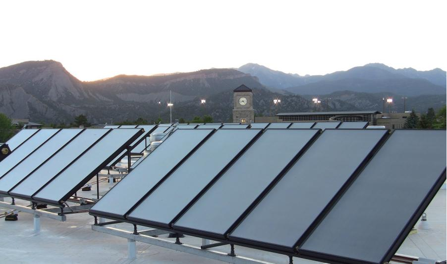
Mist beneath a solar collector’s glass can make a new installation look defective before anyone has measured its performance. The opposite mistake is to dismiss every cloudy panel as normal condensation, even when water is collecting inside the frame.
The appearance alone does not settle the question. A useful assessment distinguishes the location of the moisture, its relationship to weather and operation, whether it clears, and whether other signs point to water entry or a hydraulic fault.
Temporary internal fogging can occur in some conventional glazed flat-plate collector designs. Persistent pooling, repeated localized wetting, damaged glazing or unexplained fluid loss requires a different response. The selected collector’s manual and construction details determine the acceptance and service criteria.
This guide is for distributors, installers and owners who need to describe the problem accurately and decide what should happen next. It focuses on conventional glazed flat-plate collectors, not vacuum-loss diagnosis in evacuated glass tubes.
First establish which surface is cloudy
Before calling the condition an internal leak, identify where the visible material sits:
| Visible condition | Initial distinction to make |
|---|---|
| Dew or droplets on the outside of the cover | External surface moisture rather than water inside the collector |
| Fine mist beneath the glass | Possible internal condensation; assess its timing and behaviour |
| Large droplets, tracks or water collecting at an edge | Investigate retained moisture, water entry and drainage conditions |
| A film that remains after an apparent drying period | Consider a deposit, contamination or material change rather than assuming liquid water |
| Moisture concentrated near an internal pipe or connection | Include a hydraulic leak in the investigation |
Use observations from a safe access position. Glazing, hot collector connections and roof edges are not suitable places for improvised inspection. A professional service visit is appropriate where the condition cannot be identified safely from photographs or normal monitoring points.
The condition of neighbouring collectors can help, but it is not a verdict. They may have different shading, airflow around the housing, operating temperatures or exposure to wind-driven rain.
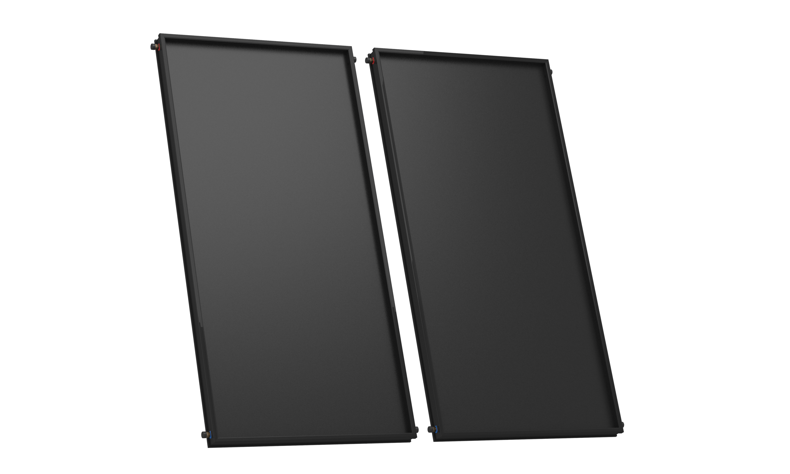
Why condensation can occur without a broken cover
Water vapour condenses when a surface is sufficiently cold relative to the surrounding air’s dew point. The U.S. National Weather Service’s dew-point explanation describes this physical relationship.
Inside a collector, the relevant conditions are those of the air and surfaces inside the housing. An outdoor humidity reading provides context, but it is not a direct measurement of that internal microclimate. A glass surface can also be cooler than the ambient air under some conditions, including overnight radiative cooling.
A glazed flat-plate collector should not be assumed to be hermetically sealed simply because it has a glass cover. Some designs include ventilation paths to manage humidity and pressure equalization. For example, the Stiebel Eltron SOL 25 Plus installation manual discusses internal misting, moisture retained during storage and ventilation openings in that particular product.
That example establishes that internal mist is not universally proof of a failed seal. It does not establish the construction, permitted drying period or repair method of a SOLETKS collector. Those details must come from the supplied model’s documentation.
Quantify the dew point before interpreting a cold surface
Relative humidity alone is insufficient because saturation vapour pressure changes with temperature. A practical near-ambient calculation over liquid water uses:
γ = ln(RH/100) + 17.62T/(243.12 + T)
Tdew = 243.12γ/(17.62 − γ)
T and Tdew are in °C, and RH is entered as a percentage. This is the inversion of the Magnus vapour-pressure relationship described by the UK National Physical Laboratory. Different treatment is needed for frost and for conditions outside the approximation’s applicable range.
NPL gives a relative uncertainty below 0.6% at 95% confidence for the vapour pressure calculated by this approximation over −45 to +60°C. That is not a 0.6% uncertainty in dew-point temperature and does not include the errors of a field humidity sensor. All temperatures in the two equations above are Celsius; the ideal-gas calculation below instead requires absolute temperature in kelvin.
Consider these hypothetical internal-air conditions:
| Air temperature | Relative humidity | Calculated dew point | Inner glass temperature | Physical interpretation |
|---|---|---|---|---|
| 18°C | 40% | 4.2°C | 10°C | Glass is above the dew point |
| 18°C | 70% | 12.4°C | 10°C | Condensation on the glass is possible |
| 20°C | 90% | 18.3°C | 17°C | Only modest surface cooling is needed |
The same 10°C glass can therefore be dry or wet depending on the moisture content of the adjacent air. Conversely, outdoor air at 70% RH does not prove that the collector cavity is also at 70% RH.
At night, the cover can lose heat by long-wave radiation to the sky, while the cavity and its materials follow a different temperature history. After sunrise, the absorber, insulation and cover also warm at different rates. Moisture can temporarily evaporate from one internal surface and condense on another. This explains why a change in the visible location of water does not necessarily mean fresh water has entered at that location.
A useful diagnostic quantity is the surface-to-dew-point margin, Tsurface − Tdew. A negative margin supports condensation under the measured conditions; a margin close to zero may be inconclusive once sensor uncertainty and temperature nonuniformity are considered. This calculation is a physical screen, not permission to open a collector to install sensors. Use existing measurement points or a manufacturer-directed assessment.
How much water can one charge of humid air produce?
An approximate moisture inventory helps distinguish a thin film from repeated water accumulation. Take an assumed 0.10 m³ free-air cavity, initially at 25°C and 70% RH. This is not a measured SOLETKS cavity volume.
Using the vapour pressure from the relationship above and the ideal-gas relation for water vapour, ρv = e/(Rv × Tabs), with Rv ≈ 461.5 J/(kg·K), e in pascals and Tabs in kelvin, gives ρv in kg/m³. The table converts that density to g/m³:
| Assumed cavity-air condition | Water vapour density | Vapour mass in 0.10 m³ |
|---|---|---|
| Initially 25°C, 70% RH | 16.08 g/m³ | 1.61 g |
| Entire air charge cooled to 10°C and saturated | 9.38 g/m³ | 0.94 g |
| Difference potentially condensed | — | 0.67 g |
This closed-volume screening calculation assumes no air exchange, liquid ingress or moisture release from materials. It shows that less than a gram of condensate can be involved in one cooling event. Spread into droplets or a film, a small mass can still be visible over part of the glazing.
A larger pool cannot automatically be blamed on the initial air charge. But it also does not prove a rain leak: repeated humid-air exchange, wet insulation or moisture retained during storage can supply additional water. A single photograph gives neither the cumulative input nor the drying history.
For the total water retained inside the housing—including vapour, liquid and moisture held in materials—the balance is:
Change in retained water = rain/wash entry + hydraulic leakage + net vapour exchange − liquid drainage.
Evaporation, condensation and moisture release from insulation redistribute that water internally; they do not create or remove it from the collector. The collector dries only when moisture actually leaves through its intended paths. This is why a clear glass surface does not prove that the insulation beneath the absorber has dried.
This balance also explains two installation problems. Obstructed drainage can retain water after its original entry has stopped. Obstructed ventilation can slow vapour removal while visible droplets repeatedly disappear and return. The repair must identify the input or removal problem rather than simply remove the visible film.
Scale the inventory to a published enclosure size
Il Pagina del prodotto SOLETKS split-system lists its BTE2.0-2 collector at 2,000 × 1,000 × 80 mm, with a 1.87 m² aperture. The 80 mm total depth includes the cover, air space, absorber, insulation and housing; it is not all free air.
Assuming a 25 mm free-air depth across the aperture, the air volume is 1.87 × 0.025 = 0.0468 m³. On the same 25°C/70% RH to 10°C cooling cycle, the single-charge condensate estimate becomes approximately 0.31 g. Uniformly distributed over 1.87 m², that would correspond to a liquid film only about 0.17 μm thick. Real condensation forms droplets and patches, so visible haze can occur with very little water.
Now assume, independently, a 50 mm mineral-wool layer at 50 kg/m³ over the same area. Its dry mass would be about 4.7 kg. At an assumed water content of 1% of dry mass, it would retain approximately 47 g of water, around 150 times the single air-charge result. The gap, insulation construction, density and moisture content are illustrative assumptions, not a verified BTE2.0-2 cutaway or a measurement of a wet collector.
The comparison is useful even without a drying forecast: moisture stored in materials can support many repeated fogging cycles after the original liquid entry has stopped. A clear cover between cycles does not distinguish a dry enclosure from a wet internal reservoir.
A drying timescale needs an air-exchange assumption
For a fixed cavity at approximately constant pressure, the ideal dry-gas inventory falls as its absolute temperature rises. Warming from 10°C to 70°C gives a displaced fraction of the initial charge of about 1 − 283.15/343.15 = 17.5%. That is a simplified thermal-breathing estimate, not a measured daily ventilation rate; wind, humidity changes and multiple temperature cycles can alter actual exchange.
To keep a moisture calculation on one consistent mass basis, assume 0.010 kg of dry air is exchanged per day at 101.3 kPa. Also assume that the average outgoing humidity ratio corresponds to 50 g/m³ of water vapour at 70°C, while incoming air is 10°C and 90% RH. Converting each condition to kilograms of vapour per kilogram of dry air gives approximately:
- Outgoing humidity ratio: 0.0527 kg/kg.
- Incoming humidity ratio: 0.00685 kg/kg.
- Net removal: 0.010 × (0.0527 − 0.00685) ≈ 0.00046 kg/day, oppure 0.46 g/day.
For reference, the conversions use e = ρvRvTabs and w ≈ 0.622e/(P − e), with pressures on the same absolute basis. Subtracting g/m³ values at different temperatures while using one unqualified exchange volume would mix reference conditions.
If the assumed exchange and moisture difference stayed constant, removing 47 g would take roughly 100 days. That is an order-of-magnitude demonstration, not a SOLETKS drying period or a reason to leave a suspected leak unattended. Wind-driven ventilation can be much faster; restricted paths and slower desorption can extend drying. As the material dries, exhaust humidity also changes, so the constant-rate estimate should not be extrapolated into a product guarantee.
Translate a pressure change into expansion-vessel displacement
A pressure record has a different physical scale from a few tenths of a gram of condensate. Consider an illustrative, separate closed loop with an ideal 18 L expansion vessel and 1.5 bar(g) pre-charge. Assuming atmospheric pressure of 1.0 bar, constant gas temperature and gas charge, and an unconstrained diaphragm, the liquid accepted by the vessel is:
Vliquid = Vnominal × (1 − pprecharge/poperating),
where both pressures in the ratio are absolute, not gauge pressures.
| Gauge operating pressure | Absolute pressure | Calculated liquid held in vessel |
|---|---|---|
| 2.5 bar(g) | 3.5 bar(a) | 18 × (1 − 2.5/3.5) = 5.14 L |
| 2.4 bar(g) | 3.4 bar(a) | 18 × (1 − 2.5/3.4) = 4.76 L |
The calculated change is approximately 0.38 L. Only if fluid and gas temperatures, gas charge, pump state, circuit configuration and other compressible volumes remain equivalent could this be used to estimate a system inventory change. It is not proof of a leak or its location. Gas-charge loss, air pockets, fluid redistribution and gauge uncertainty can change the interpretation.
For water, 0.38 L is about 380 g—over a thousand times the 0.31 g single-cycle cavity example. This explains why a confirmed hydraulic loss can supply far more moisture than one charge of humid air, even when the pressure difference looks modest.
The published pressure entry needs confirmation before applying any pressure example to the product. The SOLETKS page lists 0,6 bar for the BTE2.0-2 collector and 7 bar for the tank. An indirect coil separates those circuits, so their ratings do not need to be identical; the difference alone does not prove a typo. However, 0.6 bar would be below the pressures in the hypothetical example above. A value of 0.6 MPa would instead equal 6 bar, a tenfold difference. Confirm the unit and permitted pressure-temperature envelope from the exact collector’s label and documentation; do not silently replace bar with MPa. The example is not a BTE2.0-2 operating or test-pressure instruction.
Four possible causes require different evidence
1. Moisture condensing from air already inside the housing
This is worth considering when fine mist appears under particular weather or operating conditions and later clears. The assessment becomes more persuasive when the pattern repeats consistently, there is no standing water or persistent residue, and the installation otherwise behaves normally.
Clearing is useful evidence, but it is not enough on its own to approve the collector. Check whether the recurrence and drying behaviour are acceptable for that model and whether the manufacturer identifies any relevant commissioning or storage conditions.
2. Rain or wash water entering the enclosure
Water entry becomes a stronger possibility when wetting repeatedly follows rain or cleaning, begins around one edge or penetration, or leaves a track and a persistent wet area.
Potential inspection points include the glazing perimeter, housing joints, pipe penetrations, approved drainage features and mounting orientation. These are candidate paths for a technician to examine, not a diagnosis from a photograph.
A rain-related pattern does not prove that the perimeter gasket is the failed component. Water might reach another opening, collect because the installation does not drain as intended, or be driven by an unsuitable cleaning method.
Location can be misleading because water can travel along a joint or internal surface before collecting at the lowest point. A wet bottom corner does not necessarily locate the entry point. Installation inclination, the direction of wind-driven rain, frame joints and penetrations should be read together. The defined rain exposure in a product test also does not automatically represent a concentrated high-pressure cleaning jet.
3. Fluid escaping from the collector’s hydraulic circuit
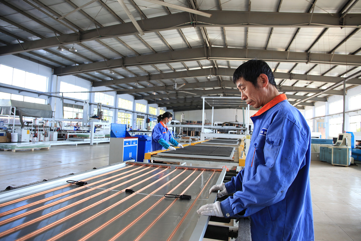
An internal absorber or connection leak can create moisture inside the housing. Relevant evidence may include local wetting, deposits, a record of fluid replenishment or pressure changes that remain unexplained after operating temperature is accounted for.
Compare pressure observations under equivalent system conditions. Pressure normally changes as the fluid heats and cools, so a hot reading followed by a lower cold reading is not, by itself, proof of leakage. Recent filling, air release and automatic make-up arrangements can also affect the interpretation.
A small leak may not produce an obvious pressure trend immediately. Conversely, a pressure loss elsewhere in the system does not prove that the cloudy collector is leaking. A qualified service assessment must connect the symptom to the actual fault location.
An automatic make-up arrangement can mask a falling pressure by replacing lost fluid, so replenishment history may be more informative than the gauge alone. Expansion-vessel condition, air removal and relief-valve discharge are additional explanations to investigate before assigning the loss to the absorber.
Fluid colour is weak evidence: water can pick up dirt or corrosion products, and not every heat-transfer fluid has an identifying colour. Where samples can be obtained through an approved service procedure, comparison with the actual loop fluid—for example its glycol concentration and condition—can provide more useful evidence. That comparison belongs with inspection and hydraulic testing; it cannot locate a leak by itself.
4. A persistent film or damaged surface
Not every cloudy appearance is moisture. Dirt, mineral residue or a material-related surface change can resemble dried condensation. Photographs should show whether droplets are present and whether the visible pattern changes with temperature and weather.
Do not open the collector or apply solvents to investigate an unidentified internal film. The glazing, absorber coating and insulation may require different handling, and the appearance may need the manufacturer’s assessment before any cleaning method is selected.
Observe the pattern through a relevant weather cycle
A useful record does not need to be complicated. It needs to preserve the details that would otherwise be lost when the sun comes out or the installer leaves.
| Observation | What to record | Why it helps |
|---|---|---|
| Collector identity | Model, serial label, position within the array | Connects the observation to the correct assembly and instructions |
| Timing | Date, time, first appearance and clearing behaviour | Distinguishes a recurring condition from a single snapshot |
| Clima | Recent rain, visible sun, approximate ambient conditions | Helps test a weather-related explanation |
| cURL Too many subrequests. | Wide photograph and close views of the affected area | Shows location, droplets, tracks and whether neighbouring units differ |
| Operating condition | Controller state and normal temperature readings | Explains whether the collector was collecting heat, cold or at a limit |
| Hydraulic history | Comparable pressure readings, alarms and replenishment | Helps identify whether fluid loss needs investigation |
| Recent work | Delivery, installation, cleaning or repairs | Identifies changes that may be relevant |
Take follow-up photographs from approximately the same position so the affected area can be compared. Record whether the collector received a meaningful period of solar exposure before concluding that it failed to dry. A shaded, cold panel and a fully exposed operating panel are not equivalent observations.
There is no universal number of hours or days after which every misted collector must be replaced. Use the manufacturer’s criteria for the specific construction and conditions. Do not wait for a long observation period where there is cracked glazing, active leakage, unsafe mounting or another condition requiring prompt service.
Compare competing explanations rather than counting symptoms
| Repeated observation | Explanation it strengthens | What it still does not establish |
|---|---|---|
| Fine haze on several units after clear, humid nights, clearing without residue | Condensation associated with the overnight temperature cycle | That every installation detail or internal material is undamaged |
| One localized track reappears after rain, including when circulation is inactive | Enclosure entry or retained rainwater | Which joint or opening is responsible |
| Wetting grows during dry-weather operation and coincides with make-up-fluid use | A hydraulic source deserves priority | That the leak is inside that collector rather than elsewhere |
| Appearance remains unchanged through warm, dry conditions | Deposit, trapped moisture or a material change | Which layer is affected or whether it is repairable |
The useful observation is one that changes the diagnosis. Another clear-afternoon photograph adds little if the disputed symptom occurs during wind-driven rain. Similarly, another pressure reading adds little if its temperature and make-up conditions differ from the previous reading. Seek a comparison that holds relevant conditions reasonably constant.
What non-invasive thermal imaging can and cannot show
A conventional long-wave thermal imager does not see the absorber through ordinary cover glass. It responds to the cover’s emitted and reflected radiation. The wavelength limitation is explained in Pulsar’s thermal-imaging guidance.
Where normal access permits inspection of the back or frame, a temperature-pattern comparison during warming or cooling can help direct an investigation. Added moisture can change conductivity, heat capacity and evaporation, but shading, thermal bridges, wind and surface emissivity can create differences too. A thermal anomaly is therefore not a moisture measurement. Comparable photographs, make-up-fluid history and matched-condition pressure records remain useful evidence without opening the enclosure.
Three illustrative service situations
The examples below are hypothetical diagnostic scenarios, not SOLETKS field cases or warranty decisions.
Scenario A: morning mist that clears across the array
Several collectors show a thin internal haze after a cool, humid night. The haze clears during solar operation. Photographs show no pool of water, persistent edge track or visible component damage, and the available operating record contains no unexplained fluid replenishment.
This pattern supports investigating temporary condensation first. Record the recurrence and compare it with the model’s guidance. Replacing every perimeter seal would be premature because the available observations have not identified a water-entry path.
The next question is whether the manufacturer regards this behaviour as acceptable for the supplied installation, not whether the collector looked clear in a single afternoon photograph.
Scenario B: one lower corner stays wet after rain
One panel repeatedly develops droplets and a visible track near the same corner following rain. Nearby panels clear, while that area remains visibly wet after comparable exposure to sun.
Here, the pattern warrants inspection of water entry, drainage, orientation and the condition of the housing. The service response should locate and correct the path, then assess whether retained water has affected insulation, the absorber or other components.
Applying sealant around every visible opening could obscure the actual path or obstruct a feature the collector requires. The repair needs the correct construction drawing and approved materials.
Scenario C: misting appears with unexplained circuit fluid loss
A cloudy collector coincides with repeated make-up-fluid additions and a pressure trend that cannot be explained by equivalent operating temperatures or recent commissioning activity. There may also be localized wetting near the absorber circuit.
This combination warrants a hydraulic investigation. Fogging alone cannot identify which pipe or joint is leaking, and an external system leak must also be considered. Follow the manufacturer’s service and shutdown procedure; do not open or depressurize a hot solar circuit to search for the source.
What not to infer from the appearance
“It clears in the sun, so there can be no damage”
Evaporation can remove visible surface moisture while leaving a water-entry path, deposits or wet insulation. Repeated localized wetting deserves investigation even if the glazing later looks clear.
“The collector is cloudy, so output has fallen by a fixed percentage”
A photograph does not quantify the optical or thermal loss. The affected area, moisture state, solar conditions, fluid temperatures and actual heat flow all matter. Avoid assigning a universal efficiency penalty to a misted cover.
There are at least two different mechanisms to separate. Droplets and films on the cover can change the light reaching the absorber. Moisture retained in insulation can increase heat loss even after the cover appears clear. Prolonged wetting can also contribute to corrosion, deposits or deterioration of internal surfaces. Their size and reversibility depend on materials and exposure; visible coverage is not a reliable conversion factor to lost kWh.
“The tank is heating slowly, so the mist is the cause”
Low delivered heat can also result from shading, poor flow, control settings, air in the circuit, heat-exchanger condition or storage behaviour. Keep the collector appearance and the system-performance investigation connected, but do not treat one as proof of the other.
“More sealant will make the collector more weatherproof”
An unapproved seal can cover drainage or ventilation features, introduce an unsuitable material or complicate later service. A repair should restore the intended construction rather than redesign it on the roof.
The separate flat-plate collector durability guide explains the relevance of glazing, seals, insulation and frame construction. This moisture assessment determines which of those components, if any, actually needs attention.

Separate a moisture symptom from a measured performance problem
Useful heat carried by the collector fluid is:
Q = ṁ × cp × (Tout − Tin).
Flow, fluid concentration and temperature measurements are therefore needed before attributing slow tank heating to the cloudy cover. A hotter collector outlet at reduced flow can still carry less heat. Tank recovery also includes piping losses, exchanger performance and the building’s simultaneous demand.
For comparable, approximately steady conditions, a familiar simplified collector-efficiency relationship is:
η = Q/(A × G) ≈ η₀ − a₁(Tm − Ta)/G − a₂(Tm − Ta)²/G.
Here A is the report’s reference area, G is irradiance in the collector plane, Tm is mean collector-fluid temperature, Ta is ambient temperature, and η₀, a₁ and a₂ are performance parameters on that same area basis. Incidence-angle effects, wind sensitivity and thermal transients may require additional treatment.
The relationship explains why two unmatched days cannot prove a moisture penalty. With the same sun, a collector operating much hotter than its surroundings normally loses more heat. Comparing a misted collector against a colder, clearer neighbour or a different flow rate mixes several effects.
As an illustrative field calculation, assume a 2.0 m² collector, G = 700 W/m², water flow of 0.020 kg/s and an 8 K fluid rise. Its measured heat would be approximately 0.670 kW, giving an instantaneous efficiency of 47.8% on that area basis. At the same flow, a 6 K rise would give 0.502 kW e 35.9%. The difference is about 167 W, but it cannot be assigned to condensation unless irradiance, operating temperature, angle, flow, transient state and measurement uncertainty are adequately accounted for. These are invented conditions, not SOLETKS test results.
A one-off field measurement also cannot identify which efficiency coefficient has changed. For that, a controlled comparison or an appropriate series of measurements is needed. A practical service record should first establish that reduced delivered heat persists under comparable conditions and is not explained by flow or controls.
What a rain-penetration test report can establish
Il IEA SHC guide to ISO 9806:2017, especially its rain-penetration and final-inspection sections, explains why retained water, inspection timing and installation inclination matter. It also identifies persistent internal condensation and wet insulation as possible consequences of water retention. This is useful background on the failure mechanisms; it is an older-edition guide.
As checked on September 30, 2026, ISO lists ISO 9806:2025 as the current published edition. Do not describe a 2017 guide as the latest standard or assume its clause details are unchanged in 2025. Read the edition stated on the supplied test report and the requirements of the relevant certification scheme.
For a moisture-related purchasing question, connect the report to the actual collector: model and construction variant, tested orientation, mounting configuration, stated test conditions, observations and final inspection. A general certificate image without that connection does not resolve how the proposed unit was assessed.
Rain resistance and hydraulic integrity are different questions. The first concerns water entering through the enclosure; the second concerns fluid escaping from its pressure circuit. Passing one assessment does not prove the other. Nor does a laboratory test establish that every field unit has been transported, mounted, cleaned and maintained in the tested condition. Use the report to define the expected construction and behaviour, then investigate the actual installation against them.
When to monitor, repair or consider replacement
| Finding after assessment | Appropriate direction |
|---|---|
| Behaviour consistent with the manufacturer’s permitted temporary condensation pattern, without associated damage | Keep the observation record and follow the stated monitoring guidance |
| An installation detail obstructs an intended drainage or ventilation path | Correct the installation through the approved service method and reassess |
| An identified, serviceable gasket or glazing defect | Evaluate a manufacturer-approved component repair and subsequent verification |
| Persistent wet insulation, damaged absorber surfaces or significant internal deterioration | Obtain a component-level condition assessment and compare the permitted repair with replacement |
| An internal circuit leak or fractured glazing | Arrange prompt qualified service using the model’s prescribed procedure |
| Cause remains uncertain | Obtain further observations or inspection rather than classifying the fault from appearance alone |
Not every collector allows the same repair. A removable cover on one product does not establish that another cover can be opened and resealed in the field. Likewise, access to a component does not mean it can be restored to its original condition economically or reliably.
Where replacement is proposed, confirm more than outside dimensions. Connections, pressure and temperature ratings, mounting compatibility and the replacement unit’s hydraulic behaviour must suit the array. A different collector can change flow distribution even if it occupies a similar roof area.
After a repair, verification should address the original symptom and its cause. Depending on the work, that may involve an approved leak test, inspection of the restored enclosure detail and observations through relevant operating or weather conditions. A clear photograph immediately after the work is not complete evidence that recurrent rain entry has stopped.
For an identified rain path, the service task has three parts: correct the entry or drainage defect, assess the retained-water damage, and verify behaviour after a relevant exposure. Replacing a gasket can address the first part while leaving saturated insulation unresolved. Conversely, replacing insulation without correcting the entry path can lead to the same condition again. The permitted disassembly and replacement method depends on whether that collector is designed for field service.
Questions to ask before purchasing flat-plate collectors
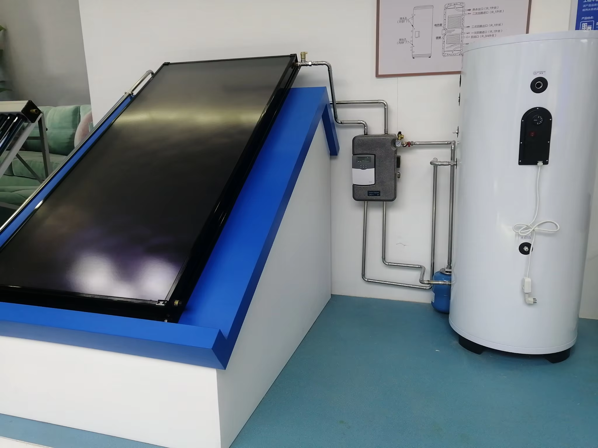
Moisture behaviour is easier to manage when the product documentation is available before installation. Ask the supplier:
- Does the selected housing have defined ventilation or drainage features, and how must they be oriented?
- What storage and transport conditions protect the collector before installation?
- What temporary condensation behaviour is addressed in the manual?
- Which observations call for a service inspection?
- Are the glazing, seals and insulation field-serviceable, and by which approved method?
- Which replacement parts are available for the exact model?
These questions reveal more about serviceability than a general statement that the collector is “fully sealed” or “maintenance free.” The product should have an explainable moisture-management design and a defined service response.
Domande frequenti
Is internal condensation always a manufacturing defect?
No. Some collector designs permit temporary internal misting under particular conditions. The model’s instructions, recurrence pattern and evidence of damage determine the assessment.
Is persistent fogging always rain entering through a gasket?
No. Retained moisture, drainage conditions, internal fluid leakage or another surface condition may need investigation. Locate the cause before specifying a repair.
Should vents be sealed or new drain holes be added?
Only a specific manufacturer-approved service instruction can establish such a modification. Another brand’s bulletin is not permission to alter a SOLETKS collector.
Can a pressure reading rule out an internal leak?
Not by itself. Interpret it with fluid temperature, operating history, filling arrangements and other observations. Small leaks or automatic replenishment may be difficult to identify from a single reading.
Can the system keep operating while the issue is assessed?
That depends on the actual condition and the model’s instructions. Temporary permitted condensation is different from damaged glass or suspected fluid leakage. Use the prescribed service response; an improvised pump shutdown can create a separate overheating problem.
Request a product-specific assessment
For a SOLETKS flat-plate collector, send the model identification, photographs and operating observations to SOLETKS. Include whether the moisture appears after rain, overnight cooling, cleaning or a change in system operation.
A useful response should identify the likely mechanism, the additional evidence needed and the approved action for that model. That gives the owner a defensible service decision and gives the installer a defined task.
Sources and scope
- Stiebel Eltron — SOL 25 Plus installation manual, equipment description and troubleshooting sections: a manufacturer-specific example documenting internal misting and moisture ventilation. Its settings, drying periods and repair methods are not applied to SOLETKS products.
- U.S. National Weather Service — Dry-bulb, wet-bulb and dew-point temperature: condensation and dew-point principles.
- National Physical Laboratory — Converting between dew point and relative humidity: the Magnus vapour-pressure approximation, range and pressure-uncertainty statement; checked September 30, 2026.
- IEA SHC — Guide to the standard ISO 9806:2017: background on rain penetration, moisture retention and final inspection; not presented as the current standard edition.
- ISO — ISO 9806:2025: current published-edition information checked on September 30, 2026.
- SOLETKS — Durable Flat Plate Solar Collectors Selection Criteria: related site content on glazing, seals, frames and insulation, checked on September 30, 2026.
- SOLETKS — Scaldacqua solare a piastre piane divise: BTE2.0-2 dimensions, aperture and the unresolved 0.6 bar pressure entry; checked September 30, 2026. The quoted 7 bar tank rating belongs to a different component and pressure boundary.
- Pulsar — Thermal imaging through glass: the 8–14 μm transmission limitation of ordinary glass; source passage checked September 30, 2026.
The dew-point, cavity-moisture, material-reservoir, drying-rate, expansion-vessel and heat-output examples use explicitly assumed conditions. Their values do not establish a SOLETKS acceptance period, operating pressure, physical diagnosis or warranty determination. Model-specific service instructions govern any intervention. In particular, the illustrative drying time is not a recommendation to postpone investigation of recurring wetting or fluid loss.