
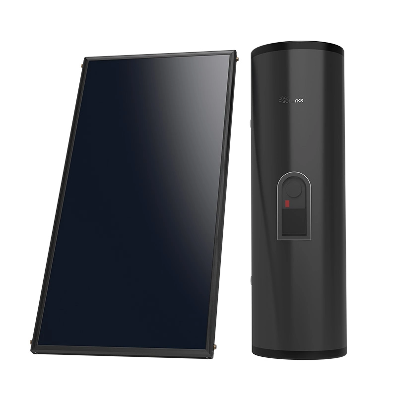
A villa split solar water heater usually places the collectors on the roof and the storage tank in a separate service area. The best tank position balances three things: a practical route to the collectors, a short route to the main hot-water outlets, and enough space for installation and future repairs.
An indoor utility room is often a strong starting point. A garage, basement or protected balcony may also work, provided the selected equipment, structure, drainage and local installation requirements support that location. The shortest pipe route is useful only if technicians can install, inspect and maintain it properly.
This guide helps owners, developers and MEP consultants compare layouts before ordering equipment. It focuses on a pumped, indirect split system. A thermosiphon or drainback system needs its own arrangement and installation instructions.
Start with the tank and the building plan together
Choose the tank capacity from the villa's hot-water demand, then check how the actual tank will enter and occupy the building. If capacity is still undecided, use the 200L versus 300L villa capacity guide first.
Toto SOLETKS split-system product page describes separate collector and tank installation and lists several tank sizes. For construction planning, request a current drawing of the selected model rather than relying on a capacity label or a generic system illustration.
Mark these items on the floor plan:
- The tank's installed footprint and total filled weight.
- The delivery route, including doorways, corners and stairs.
- The clearance needed to remove the heating element, sensors and any serviceable anode fitted to that model.
- Access to valves, the pump station, controller and electrical isolation.
- Approved drainage and the route for relief-valve discharge.
- The eventual replacement route if the tank must be removed.
A tank can fit in an empty cupboard and still be impossible to service after shelves, pipes and door frames are installed. Draw the service envelope as well as the tank outline.
Compare four practical tank locations
The following is a planning matrix, not a declaration that every model is approved for every location.
| Umiestnenie | When it is worth considering | Main question before approval |
|---|---|---|
| Utility room near the bathroom core | The collector route and main hot-water branches can both remain reasonably short | Can the tank be delivered, serviced and drained without removing permanent finishes? |
| Garage | There is convenient equipment access and room for the pump station | Is the space protected against local freezing conditions, vehicle impact and unsuitable exposure? |
| Basement plant room | The building already provides suitable plant space and drainage | What are the actual pipe lengths, static pressure requirements and route to upper-floor bathrooms? |
| Protected balcony | Indoor floor area is limited and the product permits this exposure | Have filled weight, weather protection, wind exposure, drainage and maintenance access been checked? |
For a large villa, the best compromise may sit closer to the main bathroom group than directly below the collectors. Compare both circuits before making that decision.
Keep the solar loop separate from the domestic water route
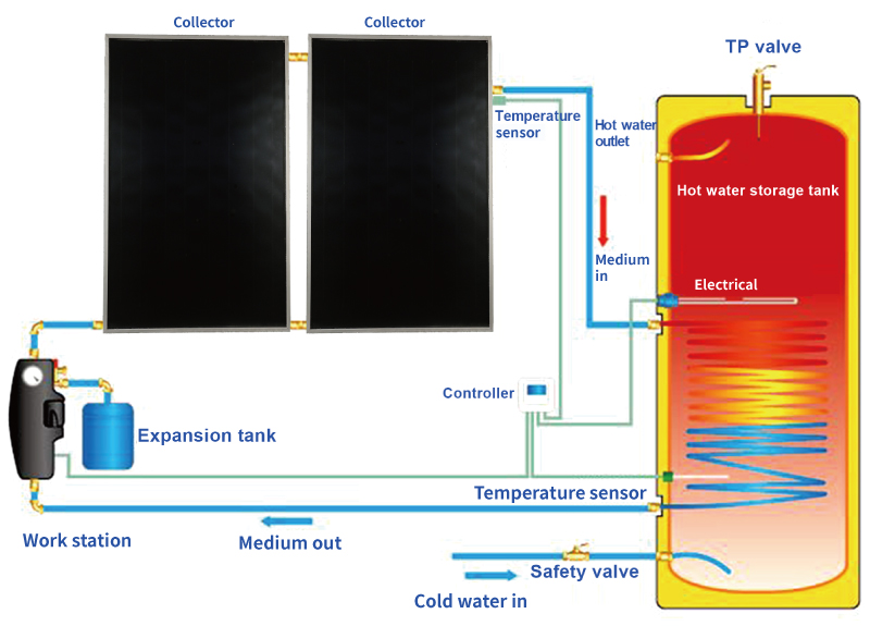
An indirect system contains distinct hydraulic paths. The collector fluid transfers heat through a heat exchanger; it does not become shower water.
SOLAR CIRCUIT — sealed heat-transfer-fluid loop

Roof collectors ── hot fluid ──> Tank heat exchanger
Roof collectors <── pump / cooled return ── Tank heat exchanger

DOMESTIC WATER — separate from collector fluid

Cold water ──> Storage tank ──> Delivery-temperature control ──> Outlets
This is a functional sketch, not a construction schematic. The installer must add the specified expansion, relief, isolation, air-management and control components in their approved positions.
On the survey drawing, label collector flow and return separately from domestic cold water, domestic hot water and any domestic recirculation return. This avoids a common estimating mistake: counting the roof-to-tank distance once when the solar loop needs two pipes.
Compare pipe routes with a simple heat-loss budget
Consider two hypothetical utility-room layouts. Layout A needs 8 metres from tank to collectors in each direction. Layout B needs 20 metres each way.
For a screening calculation only, assume both routes lose an average of 8 watts per metre of pipe over six equivalent hot operating hours. This assumed loss is not a SOLETKS specification; real losses depend on insulation, pipe size, fluid temperature and surroundings.
Daily pipe heat loss (kWh)
= total heated pipe length (m) × average loss (W/m) × hot hours ÷ 1,000
| Screening input | Layout A | Layout B |
|---|---|---|
| One-way collector route | 8 m | 20 m |
| Total solar flow and return length | 16 m | 40 m |
| Assumed average pipe loss | 8 W/m | 8 W/m |
| Assumed hot operating period | 6 h | 6 h |
| Calculated loss during that period | 0.77 kWh | 1.92 kWh |
Under these assumptions, Layout B loses about 1.15 kWh more during the period. That does not automatically rule it out. It shows the designer what must be justified by better access, a shorter domestic distribution route or another building constraint.
Do not multiply this example by 365 to promise annual savings. A real annual comparison needs seasonal temperatures, operating hours and changing solar input. Domestic hot-water and recirculation losses also need a separate allowance.
Select the pump from the complete circuit
Pipe routing affects hydraulic resistance as well as heat loss. The pump calculation must include both pipes, fittings, collectors, heat exchanger and other in-line components at the required flow and fluid conditions.
In a filled, closed circuit, roof elevation is not a continuous open-lift pumping load: the descending fluid balances the ascending fluid. Elevation still matters for static fill pressure and component pressure limits. Drainback startup is a different case. See the SOLETKS hydraulic pressure-drop guide for that distinction.
Apricus likewise treats closed-loop and drainback pump requirements separately in its AP installation manual, Section 5.5. Its numerical settings apply to its own equipment, not automatically to a SOLETKS installation.
Ask the designer for the selected pump's operating point. A model name or maximum-head rating alone does not establish the flow available in your circuit.
Make the pipe route buildable and serviceable
Before the route is approved, resolve these construction questions:
| Item on the drawing | What the installer should identify |
|---|---|
| Prechody cez strechu | Weatherproofing detail, structural fixing and access for later inspection |
| Exposed insulation | Product compatibility with solar-loop temperatures and weather protection |
| Concealed sections | Joint locations and access strategy before walls or ceilings close |
| Pipe movement | Supports and allowance for thermal expansion |
| High and low points | Filling, purging and draining arrangements appropriate to the system type |
| Sensor cables | Sensor locations and protected cable routes to the controller |
| Safety devices | Accessible positions and approved discharge paths |
Use the selected system manual for pipe materials, pressure ratings, insulation and installation geometry. An apparently convenient material used elsewhere in the house may be unsuitable for the solar circuit's temperature range.
What to request at handover
The owner should receive an as-built route drawing, identified valves and sensors, product manuals, operating settings, and the installer's commissioning results. These should establish that heat reaches the tank and that the backup and protective controls operate as specified.
A useful handover record includes measured circulation flow, relevant temperatures and pressures, the conditions during the test, and instructions for routine checks. The SOLETKS commissioning checklist provides a broader engineering framework that can be adapted to the villa's scale.
Frequently asked questions
Does the tank have to be above the collectors?
Not in the pumped split arrangement discussed here. Thermosiphon systems depend on a different circulation principle and must follow the manufacturer's required relative positions.
What is the maximum distance between collectors and tank?
There is no universal distance that fits every system. The selected manufacturer may specify a limit. Within that limit, verify heat loss, hydraulic resistance, static pressure, fluid volume and service access for the actual route.
Can the tank go in a cupboard?
Possibly, if the chosen model and installation requirements permit it. Check filled weight, drainage, access, component-removal clearances and the electrical installation before building the enclosure.
Will a larger pump fix a long pipe route?
A different pump may address inadequate circulation after proper calculation. It does not remove pipe heat loss, poor access or an unsuitable insulation system.
Request a villa layout review
Send SOLETKS a roof plan, floor plan, proposed tank location, approximate flow-and-return lengths, building height, site location and hot-water demand. Include photographs of the delivery route and any existing equipment.
Ask for a model-specific layout, confirmed equipment dimensions, hydraulic assumptions and a clear installation scope. Contact SOLETKS with your villa drawings to discuss the proposed arrangement.
References
- SOLETKS — Flat Plate Split Solar Water Heater: product configuration and separate tank placement.
- SOLETKS — Solar Collector Hydraulic Pressure Drop: circuit resistance and static-pressure distinction.
- Apricus — AP Collector Installation and Operation Manual, International V18: model-specific installation reference, especially Section 5.5.
- SOLETKS — Commercial Solar Thermal Commissioning Checklist: measurement and handover framework.